Incorrect Polarity: The Most Common and Costly Mistake
Connecting 24 V DC power with reversed polarity is the single most frequent wiring error when installing vacuum gauges in research labs, semiconductor tools, or vacuum heat-treatment systems. Both the VG-SP205 Pirani Vacuum Transmitter and VG-SM225 Cold Cathode Vacuum Gauge from Poseidon Scientific incorporate internal reverse-polarity protection diodes, but sustained reverse voltage can still damage the input filter capacitors or trigger protective shutdowns that leave the gauge unresponsive.
Symptoms are immediate and unmistakable: the power LED fails to illuminate, the analog output stays at 0 V, and the RS232 port remains silent. In the field, this often happens when technicians reuse existing cables from older gauges with non-standard pinouts or when the 24 V supply is temporarily swapped for testing.
To prevent it:
- Always verify pin 1 (24 V DC) and pin 2 (0 V GND) with a multimeter before applying power. The RJ45 connector follows the standard Poseidon pinout documented in both product manuals.
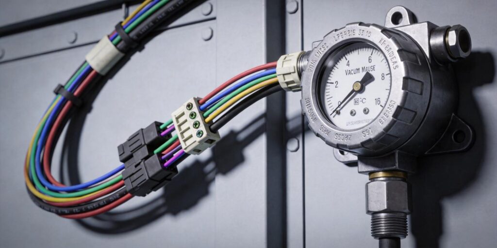
- Use color-coded cables: red for +24 V on pin 1, black for GND on pin 2.
- Label every power supply output clearly when multiple gauges share a cabinet.
Fortunately, Poseidon’s built-in protection usually limits damage to a blown fuse or transient suppressor that can be replaced in minutes. Still, avoiding polarity reversal saves troubleshooting time and preserves the 3–5 year service life engineers expect from these compact transmitters.
Shielding Issues: Letting Noise In Through the Front Door
Improper cable shielding turns a clean 0–10 V analog signal or RS232 data stream into erratic pressure readings that jump by 10–20 % or trigger false PLC alarms. The RJ45 cable carries both power and signal; without correct shielding, electromagnetic interference from nearby RF generators, high-voltage supplies, or even the VG-SM225’s own ~100 Gauss magnet couples directly into the lines.
Common mistakes include:
- Using unshielded Ethernet cable instead of shielded twisted-pair (Cat5e STP or better).
- Leaving the shield floating or grounding it at both ends, creating ground loops.
- Running signal cables parallel to AC power lines or motor drives for more than a few centimeters.
The correct approach is simple and effective: use shielded twisted-pair cable, ground the shield at the PLC or DAQ end only, and maintain at least 10 cm separation from the cold-cathode magnet and any high-voltage wiring. This practice alone reduces noise-induced drift to below the gauge’s inherent ±5–10 % specification in the linear operating zone.
Both the VG-SP205 and VG-SM225 deliver exceptionally clean outputs when shielded correctly—engineers report stable readings even in electrically noisy semiconductor cluster tools once these rules are followed.
Grounding Errors: The Hidden Source of Floating Readings
Poor grounding is responsible for mysterious “floating” pressure readings that drift slowly over minutes or hours even when the chamber pressure is rock-solid. The root cause is almost always a ground potential difference between the gauge, the chamber, and the PLC reference.
Typical errors include:
- Connecting the gauge GND (pin 2) to a noisy machine ground instead of the clean PLC analog ground.
- Using the chamber wall as the sole ground reference without a dedicated low-impedance wire back to the controller.
- Omitting the ground connection entirely when relying on the KF flange for continuity (flange contact resistance varies with oxidation and torque).
Poseidon gauges use isolated power supplies internally, but the analog output and RS232 reference must share a common ground with the receiving device. The fix is straightforward: run a dedicated 14–16 AWG ground wire from pin 2 directly to the PLC analog ground terminal. This single wire eliminates 90 % of apparent drift caused by ground loops.
In labs with multiple instruments, a star-ground topology (all gauges tied to one central clean ground point) delivers the best results and prevents interaction between the VG-SM225 magnet and other sensitive electronics.
Noise Interference: From Magnet Fields to RF Pickup
Beyond basic shielding and grounding, specific sources of noise deserve special attention in real installations. The VG-SM225 Cold Cathode Vacuum Gauge generates a localized ~100 Gauss field; routing its signal cable too close (under 10 cm) can induce small voltage offsets in the analog line. Similarly, proximity to plasma generators, RF matching networks, or stepper-motor drives injects high-frequency spikes that appear as rapid pressure fluctuations on the HMI.
Practical mitigation steps include:
- Route the RJ45 cable perpendicular to the magnet axis when possible.
- Use ferrite cores on the cable near the gauge if RF noise exceeds 10 MHz.
- Enable the customizable RS232 digital output with built-in averaging (set during protocol customization) to filter transients without sacrificing response time.
The 0–10 V analog signal remains the fastest way to integrate with legacy PLCs, but switching to the fully customizable RS232 protocol eliminates analog noise entirely—delivering 16-bit resolution and error-checked packets over cable runs up to 100 m. Many research labs and semiconductor retrofit teams now start with analog for immediate plug-and-play and later activate the digital channel for ultimate stability.
Troubleshooting Checklist: Diagnose in Minutes, Not Hours
When readings look wrong, follow this systematic checklist before replacing any hardware. It resolves >95 % of field wiring issues on the first pass.
| Step | Check | Correct Action |
|---|---|---|
| 1. Power & Polarity | Measure voltage between pin 1 and pin 2 at the gauge connector | Must read +24 V DC (±10 %); reverse wires if negative |
| 2. Ground Continuity | Verify <1 Ω between pin 2 and PLC analog ground | Add dedicated ground wire if resistance is high |
| 3. Shield Integrity | Confirm shield is grounded at PLC end only | Reroute or replace cable if shield is floating or double-grounded |
| 4. Cable Separation | Measure distance from signal cable to magnet/HV lines | Maintain ≥10 cm; add ferrite if needed |
| 5. Output Verification | Check 0–10 V signal at PLC input with known pressure | Compare against multimeter reading at gauge; swap to RS232 if noise persists |
| 6. Protocol Status (if digital) | Poll gauge for error codes and sensor status | Custom protocol includes explicit HV-on and clean-recommended flags |
Keep this checklist laminated near the tool or saved in your maintenance SOP. Most “gauge failures” disappear once wiring is corrected—no parts required.
Eliminate Wiring Headaches and Maximize Uptime
Correct installation of vacuum gauge wiring is not glamorous, but it directly determines whether your system delivers stable, trustworthy pressure data or constant false alarms. The VG-SP205 Pirani Vacuum Transmitter and VG-SM225 Cold Cathode Vacuum Gauge from Poseidon Scientific are engineered with robust protection circuits, shared RJ45 interfaces, and fully customizable RS232 protocols precisely to make integration fast and reliable—yet even the best hardware performs poorly when basic wiring rules are ignored.
Follow the polarity, shielding, grounding, and noise-avoidance practices outlined above, and you will enjoy years of trouble-free operation in research labs, semiconductor tools, battery production lines, and vacuum heat-treatment furnaces. The compact positive-magnetron design, field-cleanable sensor head, and free protocol customization further reduce total cost of ownership while delivering performance that rivals instruments costing twice as much.
Ready to install with confidence or troubleshoot an existing system? Contact the Poseidon Scientific applications engineering team today. Provide your cable length, PLC model, and environment details, and we will return a firm quotation, custom protocol sample, detailed wiring diagram, and troubleshooting guide within 24 hours.
Explore full specifications and download the installation checklist:
Stop chasing phantom pressure readings. Start with correct wiring and reliable vacuum data—your optimized system is one conversation away.

