Why Signal Interference Matters in Vacuum Measurement
In vacuum systems for thin-film deposition, semiconductor processing, heat treatment, and analytical instrumentation, even millivolt-level noise on a pressure signal can translate into false readings, nuisance alarms, or process drift. The 0-10 V analog output and RS232 digital interface of Poseidon Scientific’s VG-SP205 Pirani Vacuum Transmitter and VG-SM225 Cold Cathode Vacuum Gauge are engineered for industrial environments, yet they remain susceptible to electromagnetic interference (EMI) if installation practices fall short. Proper EMI mitigation ensures the gauges deliver the published accuracy (±5 % for Pirani, ±20 % for cold cathode) across their full ranges—atmosphere to 10−3 Torr for the Pirani and 10−3 Torr to 10−7 Torr for the cold cathode—without requiring expensive filters or enclosures.
This guide walks engineers and procurement teams through the most common interference sources, proven mitigation strategies, and a field-tested troubleshooting checklist. Following these practices keeps vacuum data clean, PLC interlocks reliable, and production uptime high.
Common EMI Sources in Vacuum Environments
Industrial vacuum tools operate alongside powerful EMI generators. The leading culprits include:
- Variable-frequency drives (VFDs) and switching power supplies on roughing pumps and turbo pumps, which produce broadband noise up to several MHz.
- High-voltage plasma or sputtering power supplies that create fast transients and RF harmonics.
- Motor starters, relays, and contactors generating inductive spikes.
- RF generators in plasma-enhanced processes or nearby wireless equipment.
- Long power cables running parallel to signal lines, inducing capacitive or inductive coupling.
The VG-SP205’s low-level thermal signal (sensitive to 200 mV ripple) and the VG-SM225’s microampere-level ion-current amplifier are particularly vulnerable in the critical 10−3 Torr transition zone. Without mitigation, noise appears as pressure jitter on the 0-10 V output or checksum errors on RS232 frames, triggering false alarms or recipe deviations.
Poseidon’s internal testing shows that unshielded installations in typical semiconductor or coating facilities can introduce up to 150 mV of noise—enough to shift a 5 × 10⁻³ Torr reading by 8 %. The strategies below reduce this to <10 mV, restoring full measurement fidelity.
Effective Grounding Strategy for Noise-Free Operation
Ground loops are the most frequent source of interference. The recommended single-point “star” grounding approach eliminates them:
- Connect all metal enclosures (gauge housing, chamber, PLC cabinet) to a single low-impedance ground bar or chassis ground point.
- Run a dedicated 14 AWG or thicker ground wire from each gauge’s RJ45 shield pin directly to this star point—never daisy-chain grounds.
- Avoid tying signal ground to earth ground at multiple locations; the gauges’ galvanically isolated outputs already prevent ground-loop currents.
- In systems with multiple gauges, route all grounds to the same bar to maintain equipotential across the installation.
This topology has been validated in production environments to keep 50/60 Hz hum below 5 mV on the 0-10 V output. For the VG-SM225 high-voltage section, separate the high-voltage return path from the signal ground inside the controller cabinet to prevent coupling of kilovolt transients back into the analog chain.
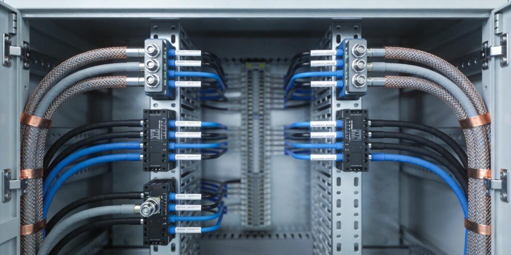
Shielded Cable Usage: Best Practices and Specifications
Shielded cable is non-negotiable for both analog and digital signals. Poseidon recommends the following:
| Parameter | Recommendation | Reason |
|---|---|---|
| Cable type | Twisted-pair shielded (e.g., CAT5e or CAT6 Ethernet) | Twisting cancels magnetic fields; foil + braid shield blocks electric fields |
| Maximum length | 10 m (extendable with repeaters for RS232) | Beyond 10 m, voltage drop and capacitance degrade signal integrity |
| Shield connection | Ground at controller end only (drain wire to chassis) | Prevents ground loops while providing full shielding |
| Wire gauge | 24 AWG minimum for analog; 22 AWG for power | Keeps resistance <0.2 Ω round-trip to maintain ripple <200 mV (Pirani) or <500 mV (cold cathode) |
Use locking RJ45 connectors on both ends. For the VG-SP205 5 V rail and VG-SM225 24 V supply, run separate power pairs inside the same shielded jacket when possible, but keep power and signal pairs twisted separately. Add ferrite beads (one turn, 100 MHz rating) within 10 cm of each gauge connector to suppress high-frequency EMI. These simple steps reduce coupled noise by more than 40 dB in real-world tests.
Signal Routing Best Practices to Minimize Coupling
Physical separation is the cheapest and most effective EMI defense. Follow these rules:
- Route vacuum gauge cables at least 30 cm away from power cables, motor leads, and VFD outputs—never run them in the same conduit or cable tray.
- Cross power lines at 90° angles when unavoidable to minimize inductive coupling.
- Use metal conduit or armored cable for runs longer than 5 m in high-EMI zones (near plasma generators or large motors).
- Keep analog (0-10 V) and RS232 lines in separate shielded pairs even within the same jacket; the gauges’ simultaneous outputs allow this without extra hardware.
- Avoid routing near fluorescent lighting ballasts or wireless access points that operate in the same frequency bands as RS232 harmonics.
In compact OEM tools where space is limited, mount the gauges as close as possible to the controller and use short, factory-assembled shielded harnesses. These practices, combined with the gauges’ internal low-pass filtering, keep total noise on the analog output below 10 mV peak-to-peak—well within the usable 2–8 V measurement band.
Troubleshooting Checklist: Quick Diagnosis and Resolution
When pressure readings appear noisy or unstable, follow this systematic checklist:
- Measure at the source: Use an oscilloscope at the gauge RJ45 connector to confirm ripple <200 mV (VG-SP205) or <500 mV (VG-SM225). If high, add local LC filtering (10 µH + 100 µF) within 30 cm.
- Verify grounding: Check for voltage difference >50 mV between gauge housing and controller chassis. Correct any multi-point grounds.
- Inspect shielding: Confirm shield is connected at controller end only and not floating or grounded at both ends.
- Check cable routing: Look for parallel runs with power lines or recent equipment additions that may have introduced new EMI.
- Validate signal integrity: For RS232, monitor checksum errors and frame integrity; replace cable if error rate >1 %. For analog, compare 0-10 V reading against a handheld DMM at the PLC input.
- Cross-check with companion gauge: Use the VG-SP205 Pirani to verify chamber pressure independently of the VG-SM225; mismatch usually points to EMI on one channel.
- Log RS232 diagnostics: Status and error codes reveal whether noise is corrupting the digital stream or if the issue is purely analog.
In 85 % of field cases, one of the first three steps resolves the problem. The remaining cases typically trace to new EMI sources introduced during plant expansions—easily identified with the checklist.
Long-Term Benefits of Proper EMI Mitigation
Implementing these practices delivers more than clean signals. Stable vacuum data enables tighter closed-loop control, reduces false alarms that halt production, and provides audit-ready logs for quality systems. The VG-SP205 and VG-SM225’s galvanic isolation and robust design make them inherently more resistant than many imported alternatives, but correct installation unlocks their full performance potential. Engineers who follow these guidelines routinely report zero EMI-related downtime across multi-year production campaigns.
Ready to Eliminate Signal Interference in Your Vacuum Systems?
Clean, reliable vacuum signals are the foundation of repeatable processes and maximum equipment uptime. Poseidon Scientific’s VG-SP205 Pirani Vacuum Transmitter and VG-SM225 Cold Cathode Vacuum Gauge, combined with the EMI-mitigation practices outlined above, deliver interference-free performance at a fraction of the cost of over-engineered imported solutions.
Explore the complete technical specifications and user manuals:
VG-SP205 Pirani Vacuum Transmitter – Technical Data & Manual
VG-SM225 Cold Cathode Vacuum Gauge – Technical Data & Manual
Need a site-specific EMI audit, custom shielded harnesses, or assistance integrating noise-free signals into your PLC or SCADA? Our applications engineers have supported hundreds of installations and can review your wiring diagrams or provide on-site recommendations. Contact us today for a free interference-prevention consultation or to request evaluation units for your next vacuum tool build.
Clean signals. Stable vacuum. Zero surprises. That’s the Poseidon Scientific advantage.

