Conductance: Why Tube Length and Diameter Change What Your Gauge Reads
In vacuum systems, gas does not flow instantly or uniformly. Conductance—the ease with which gas molecules move through a tube or orifice—creates a pressure drop between the chamber interior and any gauge mounted on an extension. In the molecular-flow regime (pressures below ~10⁻³ Torr, typical for high-vacuum processes), conductance is proportional to tube diameter cubed and inversely proportional to length. A long, narrow tube can easily cause a 20–50 % difference between true chamber pressure and the value reported at the gauge.
The equation for molecular conductance of a cylindrical tube (in L/s for air at 20 °C) is approximately:
C ≈ 12.1 × (d³ / L), where d and L are in cm.
For example, a 10 cm long KF25 tube (d ≈ 2.5 cm) has high conductance and minimal error, while a 1 m long ¼-inch tube drops conductance dramatically, producing measurable offsets during pump-down or gas introduction. This effect is negligible in viscous flow (higher pressures) but becomes dominant exactly where most research and production processes operate.
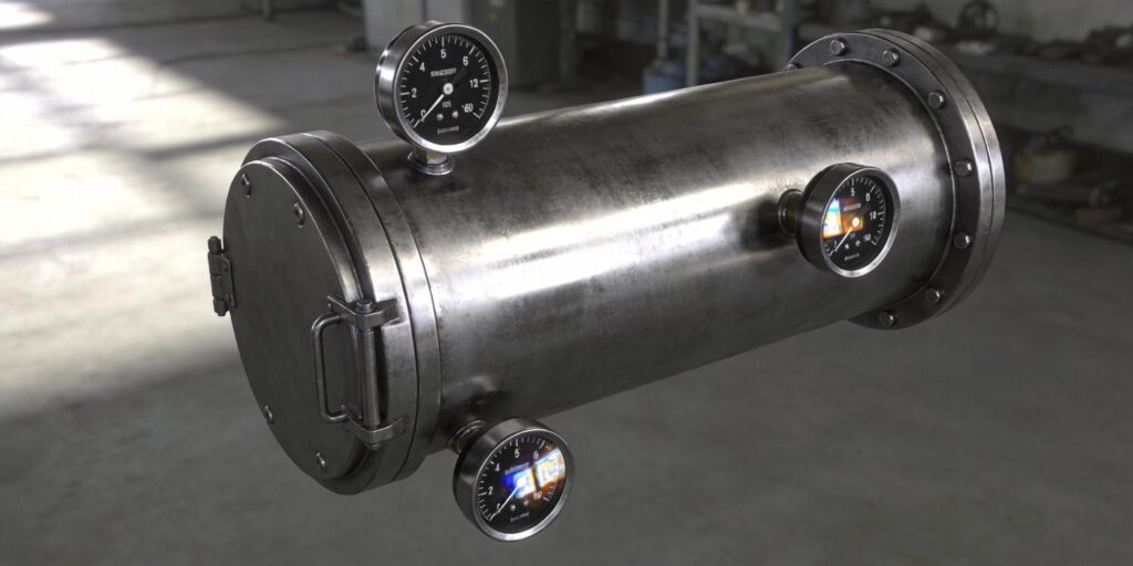
Both the VG-SP205 Pirani Vacuum Transmitter and VG-SM225 Cold Cathode Vacuum Gauge from Poseidon Scientific are designed for direct chamber mounting via standard KF16 or KF25 flanges. Their compact footprints minimize the need for extensions, eliminating conductance-induced errors that plague larger legacy instruments.
Pressure Gradients: When “Chamber Pressure” Is Not Uniform
Even inside the chamber itself, pressure is rarely perfectly uniform. During pump-down, near the pump port the pressure is lower than at the opposite wall. Gas inlets create local high-pressure zones, while hot substrates or cold traps produce thermal transpiration effects (pressure gradients driven by temperature differences). In dynamic processes—sputtering gas introduction, leak testing, or batch venting—these gradients can reach 10–30 % across a typical 300 mm chamber.
Installing the gauge on the pump foreline or a long side-arm therefore reports a value that may be 0.1–1 decade different from the actual process environment. The result: inconsistent film thickness in PVD, unreliable mass-spec ion currents, or false alarms in vacuum heat-treatment furnaces.
Poseidon’s positive-magnetron cold-cathode design (VG-SM225) and platinum-filament Pirani (VG-SP205) both support arbitrary orientation and short, wide-bore mounting. This flexibility lets engineers place the sensor exactly where the process happens—directly on the chamber wall—ensuring the reading reflects true conditions rather than a remote average.
Chamber Geometry: How Shape, Pumps, and Inlets Influence Placement
Chamber geometry dictates optimal gauge location. Spherical or cylindrical chambers with central pumps exhibit radial gradients; rectangular load-locks have corner dead zones. Gas inlets, viewports, and substrate heaters create micro-environments that a poorly placed gauge will miss.
Key geometry factors:
- Pump location: Mount gauges opposite the main pump port for representative chamber pressure.
- Gas inlet proximity: Avoid placing the gauge within 5–10 cm of inlets unless you specifically want to monitor local dosing pressure.
- Thermal zones: Keep sensors away from heated pedestals (>150 °C) unless using short extensions; both Poseidon models include full temperature compensation (15–50 °C) to handle moderate gradients.
- Conductance-limited regions: In multi-port chambers, choose the port with the shortest, widest path to the process volume.
The compact size of the VG-SM225 (significantly smaller than traditional inverted-magnetron gauges) and the maintenance-free VG-SP205 make it practical to install multiple units on complex geometries—common in modern cluster tools and research chambers—without crowding panels or adding weight.
Placement Guidelines: Best Practices for Maximum Accuracy
Follow these field-proven rules to ensure your vacuum gauge reports true chamber conditions:
Primary Recommendation
Direct chamber-wall mounting via KF16 or KF25 flange. This is the gold standard for both rough and high vacuum. No extension means no conductance loss and minimal lag during rapid pump-down.
When Extensions Are Unavoidable
- Keep length ≤10 cm and diameter ≥KF25 whenever possible.
- Use straight, smooth tubing—avoid elbows or reducers.
- For ovens or thermal-isolation needs, add a short wide-bore extension and compensate in software if needed.
Orientation and Environmental Rules
- Arbitrary orientation allowed on both Poseidon models—no preferred axis.
- For the VG-SM225, align the magnet axis parallel to nearby electron/ion beams and maintain ≥20–30 cm from sensitive components (10 cm from personnel).
- Route RJ45 cables ≥10 cm from the magnet and high-voltage lines to avoid induced noise.
Additional Tips
- Install an isolation valve upstream for easy removal during chamber cleaning.
- In dual-gauge hybrid setups (Pirani + cold cathode), mount them close together for consistent range switching at 10⁻³ Torr.
- Use the built-in software interlock on the VG-SM225 to protect electrodes during roughing phases.
These guidelines apply equally to research labs, semiconductor PVD tools, battery production lines, and vacuum heat-treatment furnaces—the exact environments for which Poseidon gauges were optimized.
Real Case Examples: What Happens When Placement Goes Wrong (and Right)
Mass-Spectrometer Source Chamber
A university core facility mounted its cold-cathode gauge on a 50 cm KF16 extension to avoid the magnet near the ion source. During pump-down, the gauge consistently read 2–3× higher than actual chamber pressure, causing premature process starts and unstable ion currents. Switching to direct wall mounting with the compact VG-SM225 eliminated the offset and reduced startup time by 40 %.
Vacuum Heat-Treatment Furnace
A commercial heat-treat shop used a foreline Pirani placement for simplicity. Readings lagged by 30–60 seconds during nitrogen backfill, triggering unnecessary alarms and extending cycle times. Relocating the VG-SP205 directly to the chamber wall via a short KF25 port restored real-time accuracy and cut cycle time by 15 %.
Battery Electrolyte-Filling Station
A gigafactory line mounted both gauges on long tube extensions to keep electronics outside the dry-room thermal zone. Conductance errors caused inconsistent wetting pressure control, leading to capacity variation across cells. Direct KF mounting of the hybrid Poseidon pair (VG-SP205 + VG-SM225) delivered true cavity readings, improved yield by 8 %, and simplified maintenance because the VG-SM225 head is field-cleanable without breaking vacuum.
PVD Cluster Tool Retrofit
An older tool with oversized imported gauges required panel redesign for clearance. The compact Poseidon units fit existing ports with zero modification, delivering cleaner signals and easier protocol customization for the existing PLC. Stray-field issues vanished, and electrode cleaning intervals doubled thanks to the removable sensor head.
In every case, proper placement—enabled by the small size and flexible mounting of Poseidon gauges—converted marginal performance into production-ready stability.
Ready to Eliminate Placement-Induced Errors in Your Vacuum System?
Vacuum gauge placement is not a minor detail—it directly determines whether your readings reflect true process conditions or a distorted average. By understanding conductance, pressure gradients, and chamber geometry, and following the simple guidelines above, engineers achieve repeatable, trustworthy data across research, semiconductor, battery, and heat-treatment applications.
The VG-SP205 Pirani Vacuum Transmitter and VG-SM225 Cold Cathode Vacuum Gauge were engineered from the ground up to make best-practice placement easy: compact footprints, KF16/KF25 direct mounting, arbitrary orientation, shared RJ45 interfaces, and customizable RS232 protocols from just 5–10 units. Their field-cleanable high-vacuum head and maintenance-free Pirani design further reduce total cost of ownership while delivering performance that rivals instruments costing twice as much.
Contact the Poseidon Scientific applications engineering team today for a no-obligation consultation. Share your chamber geometry, process pressures, and integration needs, and receive a firm quotation, detailed placement diagram, and performance recommendation within 24 hours.
Explore full specifications and request an evaluation kit:
Place it right. Measure it right. Start your optimized vacuum system today.

