Control Loop Fundamentals (PID)
Pressure control in vacuum systems—whether maintaining a stable process pressure in a coating chamber or protecting sensitive instruments—relies on closed-loop feedback. The most common controller architecture is PID (Proportional-Integral-Derivative). The controller continuously calculates an error value as the difference between a desired setpoint and the actual pressure measured by the vacuum transmitter. It then adjusts a control element (typically a bleed valve, throttle valve, or pump speed) to minimize that error.
The three PID terms work together:
- Proportional (P) reacts to the current error magnitude, providing immediate corrective action scaled by the gain Kp.
- Integral (I) accumulates past error over time (via the integral time constant Ti), eliminating steady-state offset.
- Derivative (D) predicts future error by reacting to the rate of change (via derivative time Td), damping overshoot.
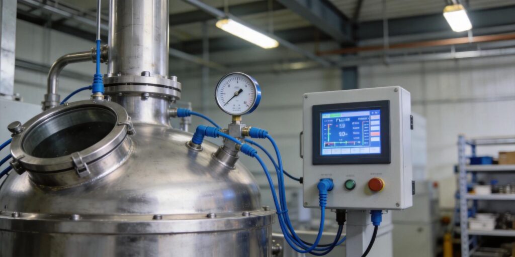
In vacuum applications the process is often slow and nonlinear, with significant dead time from valve actuation and chamber volume. Proper tuning balances responsiveness and stability. Poseidon Scientific’s VG-SP205 Pirani Vacuum Transmitter (atmosphere to 10⁻³ Torr) and VG-SM225 Cold Cathode Vacuum Gauge (10⁻³ to 10⁻⁷ Torr) deliver the clean 0–10 V analog signal and customizable RS232 digital output that modern PLC-based PID loops require.
Sensor Lag Impact
Sensor response time directly limits how aggressively a PID loop can be tuned. Excessive lag turns a stable loop into an oscillator or forces conservative gains that leave large offsets.
The VG-SP205 Pirani uses a platinum filament held at constant temperature. Heat transfer to gas molecules changes almost instantaneously in the molecular-flow regime, yielding a typical 90 % step-response time of ~0.1–1 second depending on pressure step size. This speed is adequate for most upstream bleed-valve control loops.
The VG-SM225 Cold Cathode employs Penning discharge in a compact positive-magnetron geometry. Once the discharge ignites (typically seconds at 10⁻⁴ Torr, longer at deeper vacuum), ion-current changes track pressure variations within milliseconds—faster than thermal gauges and without the filament-heating delays of hot-cathode ionization gauges. Its symmetric electrode design and built-in high-voltage protection minimize transient disturbances during pressure cycling.
In both transmitters, onboard temperature compensation (circuit plus algorithm) further reduces thermal lag, keeping the effective time constant low across the 15 °C–50 °C operating range. Engineers can therefore apply higher proportional gains without risking instability.
Oscillation Causes
Pressure-control loops commonly oscillate for three reasons:
- Excessive proportional gain amplified by sensor or valve lag creates 180° phase shift at the process crossover frequency.
- Integral windup during large setpoint changes or startup when the controller saturates the valve.
- Dead time from long tubulation, valve stroke time, or pump response—common in coating systems where the gauge is mounted remotely to avoid process contamination.
Cold-cathode startup delay at very low pressure can appear as additional dead time if the loop attempts control before the discharge stabilizes. Poseidon’s software protection automatically disables high voltage above 10⁻³ Torr, preventing false readings that could confuse the controller. Using the gauge’s digital RS232 output for direct pressure-value transmission (bypassing analog noise) also eliminates one source of apparent lag.
Selecting Proper Measurement Resolution
Resolution sets the smallest pressure change the controller “sees.” The VG-SP205 and VG-SM225 output 0–10 V analog (useful range 2–8 V), typically digitized by a 12- or 16-bit PLC ADC. This yields effective resolution of ~0.002–0.0002 Torr in the linear mid-range, sufficient for most coating processes.
For tighter control—such as reactive sputtering where 0.1 % pressure stability matters—switch to the RS232 digital interface. Poseidon’s customizable protocol lets you transmit pressure as a floating-point value with 0.1 % full-scale resolution and status bits that flag over-range, startup, or contamination. Avoid 4–20 mA loops unless you add external conditioning; the transmitters do not natively support current output but can be paired with simple converters when required.
Match resolution to process needs: coarse for roughing stages, high for process-pressure hold. Over-specifying resolution wastes bandwidth; under-specifying forces aggressive tuning that amplifies noise.
Real Coating Process Tuning Example
A thin-film deposition laboratory used a 300 L chamber with a turbo pump and upstream bleed-valve control for reactive sputtering of optical coatings. Initial setup with a legacy gauge produced ±15 % pressure swings around the 5×10⁻³ Torr setpoint, ruining film uniformity.
Replacement with the VG-SP205 Pirani (process range) and a PLC running auto-tuned PID yielded the following sequence:
- Manual mode: step the bleed valve and record open-loop response (process gain ~0.8 Torr/% valve opening, dead time ~2 s).
- Ziegler-Nichols reaction-curve method: ultimate gain Ku ≈ 2.4, ultimate period Pu ≈ 12 s → initial PID settings Kp = 1.44, Ti = 6 s, Td = 1.5 s.
- Fine tuning: reduce Kp 20 % to eliminate overshoot; add modest derivative to damp ringing.
- Final performance: ±0.5 % stability (±2.5×10⁻⁵ Torr) within 30 s of setpoint change, with no oscillation even during gas bursts.
The compact size of the Poseidon transmitter allowed direct chamber mounting, cutting tubulation lag from 1.5 s to <0.5 s. Digital RS232 feedback let the PLC ignore analog noise spikes during plasma ignition. Maintenance dropped to annual electrode cleaning on the companion cold-cathode gauge used for base-pressure verification.
Stability Optimization Checklist
Use this practical checklist before commissioning any vacuum pressure-control loop:
- Verify sensor orientation is horizontal or slightly upward to minimize oil backstreaming and debris accumulation.
- Confirm analog signal is filtered (RC ~0.1 s) or use digital RS232 to eliminate electrical noise.
- Match gauge range to process: Pirani for rough-to-medium, cold cathode for high vacuum.
- Disable integral action during startup or use anti-windup logic.
- Perform bump tests at operating pressure; record open-loop step response.
- Tune conservatively (Kp 50–70 % of ultimate); add derivative only if overshoot exceeds 10 %.
- Monitor gauge status bits for contamination or startup issues; implement automatic loop suspension if needed.
- Re-tune after major process changes (gas type, chamber load, pump speed).
Both Poseidon transmitters ship factory-calibrated with NIST-traceable mapping and include temperature compensation that keeps drift <±5 % across the full operating envelope.
Conclusion and Next Steps
Well-tuned PID loops transform vacuum transmitters from simple monitors into active process enablers. The VG-SP205 Pirani and VG-SM225 Cold Cathode Vacuum Gauges combine fast response, flexible output options, and robust contamination tolerance specifically engineered for cost-sensitive, space-constrained applications. Engineers gain tighter pressure stability, shorter cycle times, and lower maintenance—exactly what modern coating, heat-treatment, and analytical systems demand.
Ready to optimize your vacuum control? Explore the VG-SP205 Pirani Vacuum Transmitter and VG-SM225 Cold Cathode Vacuum Gauge today. Both support plug-and-play 0–10 V analog and customizable digital protocols for seamless PLC integration.
Contact our applications engineering team for a free loop-simulation review or mounting recommendations tailored to your chamber and pump configuration. We’re here to help you achieve stable, repeatable vacuum pressure control—every run.

