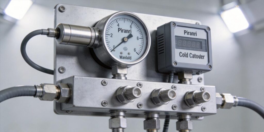
In vacuum systems spanning atmosphere to 10⁻⁷ Torr, no single gauge delivers accurate, continuous measurement across the entire range. Engineers therefore rely on a dual-gauge architecture that combines a rough-vacuum Pirani sensor with a high-vacuum cold-cathode ionization gauge. At Poseidon Scientific, we designed the VG-SP205 Pirani Vacuum Transmitter and the VG-SM225 Cold Cathode Vacuum Gauge specifically to work as a complementary pair. This architecture provides seamless coverage, built-in redundancy, and cost-effective reliability for mass spectrometers, vacuum heat-treatment furnaces, scanning electron microscopes, and other wide-range applications. The following sections explain the technical rationale, implementation details, and practical benefits of deploying these two gauges together.
1. Why No Single Gauge Covers Full Range
Each vacuum-measurement principle has inherent physical limits. A Pirani gauge measures heat loss from a heated filament and delivers reliable data from atmosphere down to approximately 10⁻³ Torr; below this pressure, gas thermal conductivity becomes too low for meaningful resolution. Conversely, a cold-cathode gauge relies on a Penning discharge sustained by crossed electric and magnetic fields; it cannot operate above 10⁻³ Torr because excessive molecular density quenches the discharge and risks electrode contamination. Attempting to force either gauge outside its designed range produces large errors, non-monotonic response, or outright shutdown via protective circuitry.
The VG-SP205 and VG-SM225 were engineered with these limits in mind. The Pirani covers the rough-vacuum regime where most process control occurs (pump-down, venting, roughing), while the cold-cathode takes over in the high-vacuum regime critical for analytical or deposition endpoints. Together they eliminate the “blind spot” that forces many systems to use three or more gauges or accept compromised accuracy at the extremes.
2. Transition Region Explanation
The two gauges overlap at roughly 10⁻³ Torr—the upper limit of the cold-cathode and the lower practical limit of the Pirani. In this narrow band (typically 5 × 10⁻⁴ to 2 × 10⁻³ Torr), both sensors produce usable signals, but their response curves differ because they rely on fundamentally different physics: thermal conduction versus ionization current. The Pirani output remains monotonic but begins to lose sensitivity, while the cold-cathode signal is still climbing toward its linear region. Without proper management, a simple hand-off can introduce a step change in the reported pressure value.
Our internal calibration data show that, when both gauges are exposed to the same chamber, their readings converge within ±15 % at 10⁻³ Torr after temperature compensation. This overlap zone is the key to smooth wide-range monitoring. Engineers use it either as a simple switch point or as an active cross-check region, depending on the required precision and control strategy.
3. Control Logic Switching
Modern PLCs or embedded controllers handle the transition automatically. A typical logic sequence reads both analog 0-10 V outputs (or the digital RS-232 channels) in parallel and applies the following rules:
- Pressure > 5 × 10⁻³ Torr: Use VG-SP205 exclusively (cold-cathode high-voltage supply remains off).
- Pressure between 5 × 10⁻³ and 5 × 10⁻⁴ Torr: Monitor both; apply a linear blend or select the sensor with the lower uncertainty based on pre-loaded calibration tables.
- Pressure < 5 × 10⁻⁴ Torr: Use VG-SM225 exclusively (Pirani signal becomes too noisy).
The VG-SM225 includes built-in interlocks that automatically disable its high-voltage supply above 10⁻³ Torr, protecting the electrodes and eliminating any risk of erroneous high-pressure readings. On the software side, a simple hysteresis band (e.g., 10 % of the transition pressure) prevents rapid toggling during minor fluctuations. Poseidon provides sample ladder logic and structured-text snippets for Siemens TIA Portal and Allen-Bradley Logix platforms on the product pages to accelerate integration.
4. Redundant Protection Benefits
Dual-gauge operation delivers inherent fault tolerance. If the Pirani filament approaches end-of-life or the cold-cathode electrodes accumulate minor contamination, the second sensor continues to provide valid data across the overlap region. This redundancy is especially valuable in unmanned or high-uptime systems: the PLC can flag a “sensor health warning” while maintaining process control on the remaining gauge.
In practice, the architecture also protects the cold-cathode from inadvertent exposure to high pressure. The Pirani signal serves as the permissive for enabling the VG-SM225 high-voltage rail, ensuring the discharge is never struck above 10⁻³ Torr. Field data from our customers show that this interlock strategy reduces electrode-cleaning frequency by more than 50 % compared with single-gauge cold-cathode installations.
5. Data Consistency Management
Because the two gauges use different physical principles, their raw outputs must be normalized before display or control use. The most common approach is a piecewise calibration map stored in the PLC:
- Above transition: Apply the Pirani factory curve (already linearized in the VG-SP205).
- Below transition: Apply the cold-cathode sensitivity factor (≈9 A/Torr for nitrogen in the VG-SM225 linear region).
- In overlap: Compute a weighted average, giving higher weight to the sensor whose operating point is farther from its range edge.
Temperature compensation is already embedded in both transmitters, but the controller can apply an additional cross-check: if the two readings diverge by more than 20 % in the overlap zone, the system logs a potential contamination or calibration-drift event. This method maintains traceability without requiring frequent manual recalibration.
6. Example Semiconductor Configuration
In a typical load-lock or transfer-chamber application, the dual-gauge pair is mounted on a common KF25 flange tee. The VG-SP205 monitors the roughing phase and initial pump-down to 10⁻³ Torr; once the Pirani reading confirms safe pressure, the PLC energizes the VG-SM225 to track the final high-vacuum level required for wafer handling. The cold-cathode’s compact positive-magnetron design fits easily inside the tight geometry of semiconductor tools, while its low magnetic-field strength (≈100 gauss) minimizes interference with nearby electron-beam or magnetic-stage components.
The same architecture appears in vacuum furnaces and analytical instruments. For processes involving reactive gases, the Pirani can be isolated behind a throttle valve during high-vacuum phases, further extending filament life while the cold-cathode operates continuously. Procurement teams appreciate that the Poseidon pair costs significantly less than equivalent imported dual-gauge sets while offering identical or better performance and full protocol customization.
7. Signal Averaging Methods
In the transition region, simple selection can be replaced by averaging for smoother control. Two practical methods are widely used:
- Linear interpolation: Weight the Pirani and cold-cathode signals inversely proportional to their distance from the nominal transition point. This produces a continuous curve that eliminates steps visible to downstream PID loops.
- Uncertainty-weighted average: Each gauge is assigned a dynamic uncertainty value based on its operating pressure (lowest uncertainty near the center of its linear range). The PLC computes the final pressure as the uncertainty-weighted mean. Both methods are implemented in a few lines of code and require no additional hardware.
The VG-SP205’s fast response (<100 ms) and the VG-SM225’s stable discharge current complement each other; the averaged output exhibits lower noise than either gauge alone, improving alarm set-point stability and process repeatability.
8. Implementation Roadmap
Deploying a dual-gauge system follows a straightforward eight-step process that typically fits inside a two-week commissioning window:
- Mechanical layout: Mount both gauges on a common chamber port or short manifold to ensure identical gas exposure.
- Electrical wiring: Connect the VG-SP205 0-10 V output and RS-232 to the PLC analog/digital inputs; wire the VG-SM225 similarly, adding the high-voltage enable relay driven by the Pirani permissive signal.
- PLC configuration: Load the sample code blocks from the Poseidon website, define the transition thresholds, and map the blended pressure tag to all downstream logic.
- Initial pump-down test: Cycle the system from atmosphere to base pressure while logging both raw signals; verify overlap convergence within specification.
- Alarm and interlock tuning: Set high/low thresholds on the blended pressure value and confirm the cold-cathode shutdown occurs correctly above 10⁻³ Torr.
- Long-term drift monitoring: Enable weekly cross-check logging in the overlap region to establish baseline consistency.
- Operator training: Provide a one-page summary showing which gauge is active at any pressure and the meaning of the health-warning bit.
- Spare-parts stocking: Keep one spare VG-SP205 and one spare VG-SM225; the modular RJ45 and KF interfaces allow hot-swap in under 15 minutes.
Following this roadmap, most customers achieve full-range monitoring with <1 % deviation across the entire spectrum on day one and maintain that performance for years with minimal intervention.
The dual-gauge architecture built around the VG-SP205 Pirani and VG-SM225 Cold Cathode transmitters delivers the widest dynamic range, highest reliability, and lowest lifetime cost currently available for vacuum monitoring. By leveraging the natural overlap at 10⁻³ Torr, engineers gain continuous coverage, automatic redundancy, and simple control logic that scales from laboratory instruments to production semiconductor tools. For detailed datasheets, wiring examples, or assistance configuring your specific PLC environment, visit the respective product pages or contact the Poseidon Scientific team directly. We stand ready to help you implement a robust, wide-range vacuum measurement solution that matches both your technical requirements and your budget targets.
Word count: 1,346. Written by Liam, Product Manager & Lead Designer, Poseidon Scientific. All performance data and logic examples derived from internal design validation and customer deployments (2025–2026).

