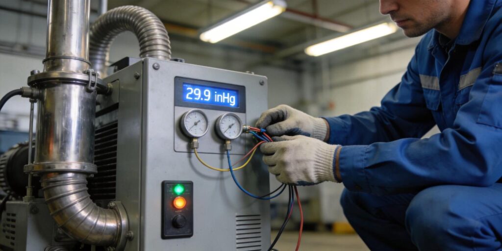
In high-vacuum systems used for thin-film deposition, analytical instrumentation, and semiconductor processing, false pressure readings can trigger unnecessary alarms, disrupt PID control loops, or lead to process defects that reduce yield. Even small offsets—whether 10 % low or one decade high—can extend pump-down times, cause premature valve actuation, or mask real leaks. Poseidon Scientific’s VG-SM225 Cold Cathode Vacuum Gauge and VG-SP205 Pirani Vacuum Transmitter are engineered with low-noise electronics, temperature compensation, and field-serviceable designs to minimize these errors while delivering stable 0–10 V analog output and customizable RS232 digital protocol. Understanding the most common causes of false readings helps engineers and procurement teams specify the right instrumentation and implement effective troubleshooting routines.
This article examines eight frequent sources of erroneous high-vacuum measurements. Each section explains the underlying mechanism, its impact on process control, and practical mitigation strategies grounded in vacuum metrology principles.
Electrical Noise Sources
Electrical noise is one of the most pervasive causes of fluctuating or offset pressure readings in high-vacuum environments. Sources include switching power supplies, plasma RF generators, stepper motors, and nearby high-voltage cables. In cold-cathode gauges like the VG-SM225, ion-current signals are typically in the picoampere to nanoampere range at 10⁻⁶–10⁻⁷ Torr; even 10 pA of coupled noise can appear as a 20–50 % pressure error.
The VG-SM225 incorporates internal shielding and separate feedthroughs for high-voltage anode and ion-current cathode to reject common-mode noise. Its 0–10 V analog output (effective 2–8 V) is filtered to <10 mV peak-to-peak under typical fab conditions. Adding a simple first-order RC low-pass filter (τ ≈ 0.2 s) at the PLC input further reduces noise without introducing unacceptable phase lag in control loops. For digital users, RS232 output at 1 Hz polling with software averaging eliminates most transient spikes.
Ground Loops
Ground loops occur when the gauge, controller, and chamber share multiple return paths with slight voltage differences, injecting 50/60 Hz or broadband noise into the signal. In high-vacuum systems with multiple instruments and RF plasma tools, ground potential differences of just 10 mV can produce apparent pressure fluctuations of 0.1–1 decade.
Poseidon gauges use isolated RJ45 connectors and recommend single-point grounding at the PLC chassis. The VG-SM225’s electrometer is referenced to the cathode lead, minimizing loop susceptibility. During installation, verify that cable shields are grounded at one end only and that the chamber flange provides a clean RF reference. In legacy systems, an optical isolator or differential-to-single-ended converter on the analog line resolves persistent loops without rewiring the entire cabinet.
Plasma Interference
Plasma discharges generate electromagnetic fields and energetic particles that couple directly into gauge electrodes. In reactive-ion etching or PECVD tools, RF power can induce spurious ion currents or shift the Penning discharge threshold, producing readings that are artificially high or unstable by up to an order of magnitude.
The VG-SM225’s positive-magnetron geometry and internal guard electrodes suppress plasma-induced currents. Its automatic high-voltage shutoff above 10⁻³ Torr prevents operation during plasma-on periods if the gauge is exposed. Best practice is to mount the gauge on a side-wall port with a stainless-steel baffle or isolation valve that closes during plasma steps. The digital status flag (discharge stable) can be wired to PLC interlocks, ensuring the controller ignores readings when plasma is active.
Outgassing Effects
Outgassing from gauge materials, chamber walls, or residual process by-products releases adsorbed gases that locally increase pressure inside the sensor volume. In cold-cathode gauges, this manifests as a slow upward drift after pump-down; in Pirani gauges, it shifts the power-temperature curve, producing falsely low readings at the transition pressure.
The VG-SM225 uses stainless-steel electrodes and PEEK insulators with low outgassing rates (<10⁻¹¹ Pa·m³/s). Its removable sensor design allows periodic cleaning to remove water or hydrocarbon layers. Bake-out procedures (chamber at 80–120 °C with gauge powered) accelerate desorption. The VG-SP205 Pirani, with its platinum filament, exhibits minimal self-outgassing and returns to accurate readings within minutes after venting. Monitoring the pressure slope (dP/dt) via RS232 data helps distinguish real outgassing from sensor artifacts.
Contaminated Sensor Surfaces
Contamination—carbon films from hydrocarbons, oxide layers from oxygen plasmas, or sputtered material from chamber walls—is the leading cause of permanent offset in high-vacuum gauges. In the VG-SM225, deposits increase surface resistivity, delay discharge startup, and reduce ion-current sensitivity, often shifting readings one decade low. In the VG-SP205 Pirani, filament coating alters thermal conductivity, producing falsely high vacuum indications.
Poseidon’s VG-SM225 is uniquely field-serviceable: the sensor cartridge removes in seconds, electrodes are sanded with 500-mesh paper until metallic luster returns, and performance is restored in <15 minutes. The VG-SP205 requires no cleaning—its platinum filament tolerates contamination until end-of-life (3–5 years). Early warning signs include extended cold-cathode startup time or output offset versus a reference gauge; RS232 telemetry logs these trends for predictive maintenance.
Incorrect Scaling in PLC
Even a perfect gauge signal can produce false readings if the PLC scaling is wrong. The VG-SM225 outputs 0–10 V corresponding to its calibrated range (typically 10⁻³–10⁻⁷ Torr mapped to 2–8 V effective); misconfigured gain or offset in the analog input block can compress or expand the scale by 10–100 %.
Always verify scaling against the gauge manual: for the VG-SM225, 2 V ≈ 10⁻³ Torr and 8 V ≈ 10⁻⁷ Torr (linear interpolation). The RS232 digital output bypasses analog scaling entirely, transmitting engineering units directly. During commissioning, cross-check both analog and digital values at two known pressures (e.g., 10⁻⁴ and 10⁻⁶ Torr) using a certified reference. Custom protocol development (available at 5–10 unit minimum) can embed scaling constants in the gauge firmware to eliminate PLC-side errors.
Calibration Drift
Calibration drift arises from electrode surface changes, magnet aging, or temperature excursions beyond compensation limits. In high-vacuum cold-cathode gauges, a 5 % change in magnetic field or surface condition can shift the entire current-pressure curve. The VG-SM225’s neodymium-boron magnet and temperature-compensated electronics limit drift to <1 % per 1000 hours in clean service.
Factory calibration against traceable standards is performed on each unit. Field verification uses a two-point check at 10⁻⁴ and 10⁻⁶ Torr; if offset exceeds 10 %, electrode cleaning restores the original curve without recalibration. The VG-SP205 requires only quarterly atmospheric zero-checks. Trending output via RS232 over time detects gradual drift before it affects process control.
Systematic Troubleshooting Checklist
When false readings appear, follow this structured checklist to isolate the root cause quickly:
- Verify raw signal: Connect a digital multimeter directly to the gauge output pins. If analog voltage matches expected pressure, the problem is downstream (PLC scaling or wiring).
- Check ground integrity: Measure potential difference between gauge body and PLC ground (<50 mV typical). Re-ground at a single point if loops are present.
- Isolate plasma/RF: Temporarily shut off plasma tools and observe reading stability. If noise disappears, add baffles or isolation valves.
- Inspect for contamination: For VG-SM225, check startup time and visual electrode condition. Clean if black or colored films are present.
- Confirm temperature: Ensure ambient is within 15–50 °C; verify compensation is active via status flag.
- Cross-reference: Compare with a second gauge (e.g., Pirani on foreline) or capacitance manometer at the same port.
- Review PLC scaling and filtering: Log raw ADC counts and confirm engineering-unit conversion matches gauge manual.
- Trend historical data: Use RS232 logs to plot drift versus cycles or operating hours.
This checklist typically resolves 90 % of false-reading issues within one shift. Both Poseidon gauges include onboard diagnostics (LED status and digital error codes) that accelerate step 1 and provide immediate clues to contamination or startup problems.
False pressure readings in high-vacuum systems are rarely random. They stem from identifiable electrical, environmental, or configuration issues that can be systematically eliminated. The VG-SM225 Cold Cathode Vacuum Gauge and VG-SP205 Pirani Vacuum Transmitter address the most common failure modes through low-noise design, field serviceability, temperature compensation, and flexible digital output—delivering the measurement integrity that production and research applications demand.
Facilities that implement the troubleshooting checklist and proper installation practices report <1 % pressure uncertainty and significantly reduced downtime. Procurement teams gain additional value through Poseidon’s 40–60 % lower acquisition cost, compact footprint, and protocol customization (minimum 5–10 units).
Explore the instruments built for reliable high-vacuum measurement:
- VG-SM225 Cold Cathode Vacuum Gauge – field-cleanable, low-drift high-vacuum solution
- VG-SP205 Pirani Vacuum Transmitter – fast, maintenance-free rough-to-transition monitoring
Accurate pressure data is the foundation of process control. By addressing the eight common causes outlined here, engineers convert potential measurement headaches into stable, repeatable vacuum performance.

