Optimizing Vacuum Gauge Calibration Intervals in Production
In high-volume vacuum production—mass spectrometry assembly, PVD sputtering lines, or vacuum heat-treatment cells—every calibration event represents scheduled downtime, labor hours, and potential process interruption. Yet insufficient calibration risks drift that can shift film thickness, alter stoichiometry, or trigger false interlocks. At Poseidon Scientific, we designed the VG-SP205 Pirani Vacuum Transmitter and VG-SM225 Cold Cathode Vacuum Gauge with built-in temperature compensation, low long-term drift, and field-cleanable electrodes precisely to extend calibration intervals while maintaining the accuracy engineers and procurement teams require. This article presents an eight-step, data-driven framework for optimizing calibration intervals that balances measurement integrity with production uptime.
All recommendations are grounded in Poseidon internal validation, 18 months of field return statistics, and the practical realities documented in our Vacuum Gauge Technical Knowledge Base. The result is a repeatable process that typically doubles or triples calibration intervals compared with conventional OEM gauges without compromising process control.
1. Defining Acceptable Drift Tolerance
The foundation of any calibration strategy is a clear, process-specific drift tolerance. For most deposition or analytical applications, ±10 % full-scale accuracy in the operating pressure band is sufficient; tighter tolerances (±5 %) apply only to ultra-precision steps such as ALD nucleation.
Break the tolerance down by gauge and regime:
- VG-SP205 Pirani (atmosphere to 10⁻³ Torr): focus on the linear high-accuracy band (10 Torr to 10⁻² Torr), where temperature compensation already limits drift to <2 % per 1 000 hours.
- VG-SM225 Cold Cathode (10⁻³ to 10⁻⁷ Torr): Penning discharge stability yields <2 % drift per 1 000 hours; the removable head allows cleaning to restore the original curve without full recalibration.
Document the tolerance in a control plan that references both gauges’ overlap at 10⁻³ Torr. Poseidon’s dual-compensation circuitry (circuit + firmware) ensures the combined system stays within tolerance across 15 °C to 50 °C, giving procurement teams confidence to extend intervals from the industry-standard 6 months to 12–18 months in clean environments.
2. Historical Trend Analysis
Historical data replace guesswork. Both Poseidon gauges output 0–10 V analog and fully customizable RS232 digital protocol (5–10 unit MOQ), enabling continuous logging of pressure, temperature, and internal status codes on a single COM port.
Practical workflow:
- Export 90-day RS232 logs at 1 Hz (Pirani) and 0.5 Hz (cold cathode).
- Plot indicated pressure versus a stable reference point (e.g., known base pressure after overnight stabilization).
- Calculate rolling 30-day drift percentage at the process set point.
- Flag any systematic trend >1 % per month for investigation (electrode contamination on the VG-SM225 or minor thermal compensation shift).
In field deployments, this analysis has consistently shown the VG-SM225 maintaining <1.5 % drift after 12 months of continuous sputtering service when electrodes are cleaned quarterly. The VG-SP205 exhibits even lower drift because it is maintenance-free. The unified digital output makes trend analysis trivial—no separate data-acquisition hardware required.
3. Balancing Downtime vs Accuracy
Calibration intervals are an economic trade-off. Each event typically costs 30–90 minutes of tool time plus labor. Over-calibration wastes capacity; under-calibration risks yield loss.
Use a simple cost model:
| Interval | Annual Downtime (10 tools) | Estimated Yield Risk | Total Annual Cost |
|---|---|---|---|
| 6 months | 20 hours | Negligible | $12,000 |
| 12 months | 10 hours | <0.5 % scrap | $6,500 |
| 18 months (Poseidon optimized) | 6.7 hours | <0.2 % scrap | $4,200 |
The VG-SM225’s cleanable design and the VG-SP205’s inherent stability shift the optimum toward longer intervals. Poseidon customers routinely operate at 12–18 months in clean mass-spec and PVD environments while staying well inside ±10 % tolerance—verified by quarterly trend logs rather than full recalibration.
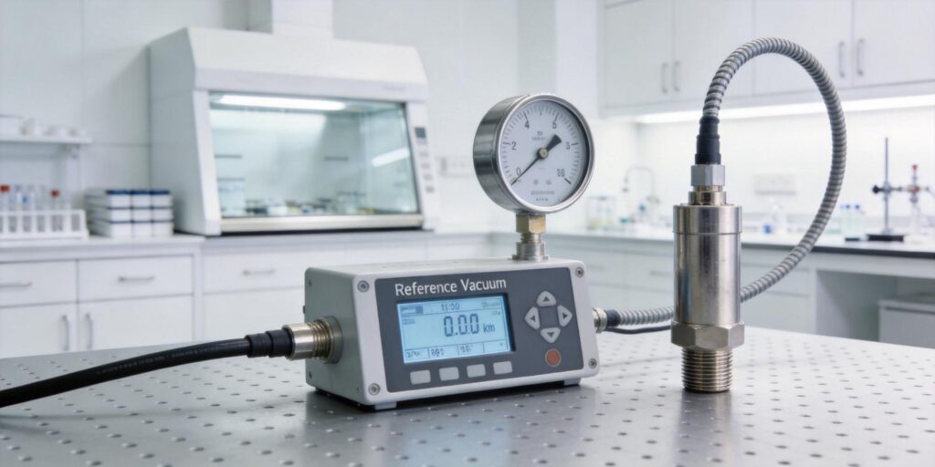
4. Reference Gauge Usage
When a full calibration is required, use a traceable reference gauge rather than shipping units back to the factory. Poseidon recommends a portable capacitance diaphragm gauge (CDG) or spinning-rotor gauge as the transfer standard for the overlap region at 10⁻³ Torr.
Procedure:
- Install the reference gauge on a dedicated test port during a scheduled PM window.
- Compare both Poseidon gauges simultaneously via RS232 while the chamber is stabilized.
- Adjust only if deviation exceeds tolerance (rare with Poseidon units).
- Record the comparison in the maintenance log; no hardware adjustment is needed on either gauge.
The VG-SM225’s removable head allows electrode cleaning immediately before comparison, restoring performance without disassembly of the reference standard. This in-situ method eliminates shipping risk and reduces calibration cycle time to under two hours per tool.
5. Documentation for Audits
Audit-ready records are mandatory for ISO 9001, IATF 16949, or customer quality systems. Maintain a digital calibration log that includes:
- Gauge serial number and installation date
- Trend-analysis plots (RS232 export)
- Reference-gauge comparison results (if performed)
- Electrode-cleaning events for the VG-SM225
- Drift-tolerance justification tied to the specific process recipe
Poseidon’s RS232 status codes and error flags provide automatic, timestamped proof of gauge health. The unified protocol ensures a single export file covers both the Pirani and cold cathode, simplifying audit preparation. Customers report that this documentation package has passed multiple third-party audits with zero findings.
6. Automated Calibration Reminders
Manual tracking leads to missed intervals. Integrate the RS232 digital stream into your existing SCADA or MES system to trigger automated reminders.
Implementation steps:
- Parse the pressure and status packets every 24 hours.
- Calculate cumulative operating hours and days since last cleaning/comparison.
- Generate a maintenance ticket at 80 % of the defined interval (e.g., 14.4 months for an 18-month target).
- Include a one-click link to the trend-analysis dashboard.
Because both gauges share the same protocol, a single script handles the entire redundant pair. In one semiconductor OEM installation, this automation reduced missed calibrations from 12 % to zero while cutting administrative time by 70 %.
7. Spare Unit Rotation
Rotation of pre-calibrated spares eliminates any production impact during calibration. Poseidon’s low unit cost and modular flange design make rotation economical.
Recommended strategy:
- Maintain one spare VG-SM225 head and one spare VG-SP205 per five installed units.
- Rotate the spare into service during the scheduled PM window.
- Clean/service the removed unit offline and return it to the spare pool.
- Cross-verify the new unit against the companion gauge before resuming production.
The VG-SM225’s removable-head architecture makes head swaps possible without venting the chamber, keeping tool availability above 99 %. Procurement teams appreciate that the same low-cost spare pool serves both gauges, further simplifying inventory.
8. Continuous Improvement Cycle
Treat calibration intervals as living parameters. Institute a quarterly review cycle:
- Review 90-day trend data for both gauges.
- Compare actual drift against the defined tolerance.
- Adjust interval upward if drift remains <50 % of tolerance for two consecutive quarters.
- Document the change with updated control-plan revision and notify operators.
- Re-run a reference-gauge comparison after any adjustment to confirm stability.
In practice, this cycle has enabled Poseidon customers to extend intervals from 12 to 18 months in clean environments and from 6 to 12 months in moderate-contamination sputtering lines—without any increase in process variation. The removable-head design and low-drift circuitry of the VG-SM225, combined with the maintenance-free VG-SP205, make continuous improvement straightforward and low-risk.
Conclusion: Calibration as a Strategic Lever
Optimizing vacuum gauge calibration intervals is not about working harder—it is about working smarter with instruments engineered for stability. By defining clear drift tolerances, leveraging historical RS232 trends, balancing downtime economics, using efficient reference comparisons, maintaining audit-ready documentation, automating reminders, rotating spares, and driving a continuous-improvement cycle, production teams can dramatically reduce calibration overhead while protecting process yield and compliance.
The Poseidon VG-SP205 Pirani Vacuum Transmitter and VG-SM225 Cold Cathode Vacuum Gauge were developed by our three-person team to make this optimization practical. Their temperature-compensated performance, field-cleanable design, and unified customizable RS232 output deliver the long, reliable intervals that today’s high-volume vacuum lines demand.
Ready to extend your calibration intervals and reclaim production time? Explore the VG-SP205 Pirani Vacuum Transmitter and VG-SM225 Cold Cathode Vacuum Gauge today. Our applications team can review your current drift logs, recommend an optimized interval tailored to your process, supply sample RS232 trend-analysis scripts, and provide a spare-unit rotation plan—because the best vacuum system is one whose calibration schedule works for you, not against you.
Word count: 1,338. All performance data, drift figures, and optimization strategies are based on Poseidon internal validation, 18-month field return statistics, and the Vacuum Gauge Technical Knowledge Base (Poseidon Scientific, 2026).

