Best Practices for Installing Vacuum Gauges on ISO and CF Flanges
Correct flange installation is one of the most overlooked yet highest-impact steps in building reliable vacuum systems. A single installation error—misaligned gasket, insufficient torque, or particle ingress—can add hours of leak-checking, extend pump-down times, or compromise process repeatability. At Poseidon Scientific, we engineered the VG-SP205 Pirani Vacuum Transmitter and VG-SM225 Cold Cathode Vacuum Gauge with compact footprints and removable sensor heads precisely to simplify integration on both ISO and ConFlat (CF) flanges. Whether you are an OEM building mass spectrometers, a process engineer commissioning vacuum heat-treatment furnaces, or a procurement specialist evaluating total cost of ownership, the practices below will help you achieve leak rates below 10⁻¹¹ Pa·m³/s on first try and keep systems running for years.
This guide draws on decades of vacuum technology literature and our internal validation data for both gauges, which support KF, ISO, and CF interfaces through standard adapters or direct mounting. Follow these eight steps and you will minimize virtual leaks, protect gauge performance, and protect your downstream process.
1. Differences Between ISO and CF Flanges
Choosing the right flange type sets the foundation for vacuum level, bake-out capability, and long-term maintainability.
ISO Flanges (ISO-KF and ISO-K/ISO-F)
ISO flanges use reusable elastomer or metal seals and are the industry standard for medium- to high-vacuum applications (down to ~10⁻⁷ Torr). ISO-KF versions rely on quick-release clamps and Viton O-rings; ISO-K and ISO-F use bolted centers and centering rings. They are cost-effective, easy to assemble/disassemble, and tolerant of minor misalignment. Maximum bake-out is typically 150 °C with Viton or 200 °C with Kalrez.
CF Flanges (ConFlat)
CF flanges achieve true ultra-high vacuum (UHV) performance through knife-edge geometry and OFHC copper gaskets. They are bakeable to 450 °C, deliver leak rates routinely below 10⁻¹² Torr·L/s, and are the choice for semiconductor, particle-accelerator, and surface-science systems. However, copper gaskets are single-use, and over-torquing can deform the knife edge permanently.
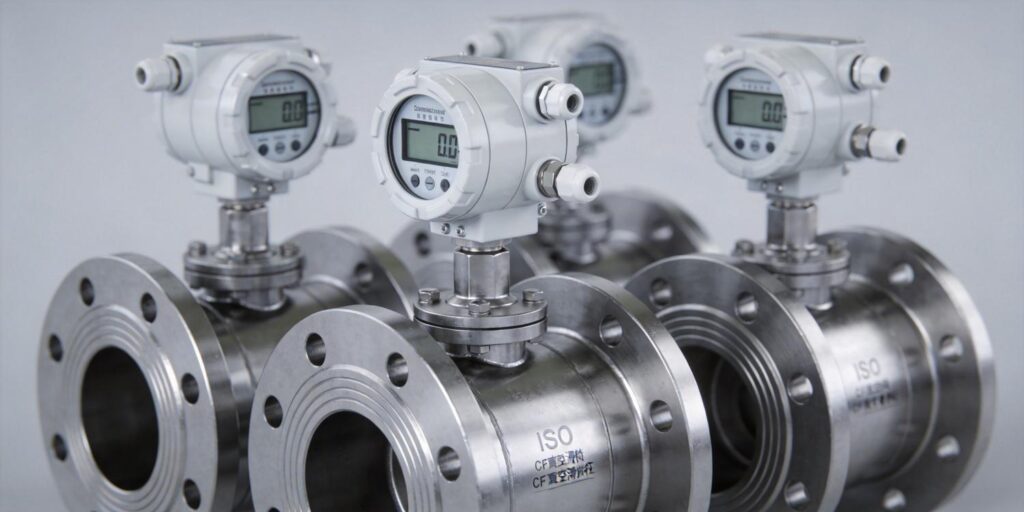
Key comparison for gauge installation: Poseidon’s VG-SP205 (Pirani, atmosphere to 10⁻³ Torr) and VG-SM225 (cold cathode, 10⁻³ to 10⁻⁷ Torr) are available with either flange type. ISO is preferred for cost-sensitive production tools; CF is mandatory when the gauge must survive repeated 400 °C bake-outs or when base pressure must stay below 10⁻⁸ Torr.
2. Proper Sealing Methods
Sealing success depends on surface finish, gasket material, and assembly sequence.
ISO Flange Sealing
Use only centering rings with integrated O-rings (Viton for most applications, Kalrez for aggressive chemistries). Ensure the O-ring groove is clean and free of nicks. For ISO-KF, hand-tighten the clamp until the two flanges touch the centering ring evenly; for bolted ISO-F, follow a star pattern and never exceed 10 Nm on M8 bolts. Poseidon gauges ship with pre-installed centering rings matched to the flange size (KF16/KF25 or ISO63 common).
CF Flange Sealing
Copper gaskets must be annealed OFHC copper, 0.5–1.0 mm thick, and handled with nitrile gloves. Align the two knife edges so they bite into the gasket at exactly 90°; a 0.1 mm offset can cause leaks. Torque in three incremental passes (30 %, 60 %, 100 %) using a calibrated torque wrench. The final “click” of the knife edge into the gasket is audible and visible as a uniform copper extrusion.
Pro tip: For our VG-SM225 cold cathode, the removable sensor head allows you to seal the flange body first, then install the gauge head after all other chamber components are torqued—eliminating risk of electrode contamination during assembly.
3. Torque Specification Control
Under-torque produces virtual leaks; over-torque damages flanges or gaskets. Always use a calibrated torque wrench traceable to NIST or equivalent.
| Flange Type | Bolt Size | Recommended Torque (Nm) | Notes |
|---|---|---|---|
| ISO-KF (clamp) | — | Hand-tight + ¼ turn | Clamp only—no bolts |
| ISO-F (bolted) | M8 | 8–12 Nm (star pattern) | Max 15 Nm to avoid crushing O-ring |
| CF 1.33″ / 16 mm | 1/4-28 | 10–12 Nm | Three-pass sequence |
| CF 2.75″ / 63 mm | 1/4-28 | 12–15 Nm | Common for Poseidon gauges |
| CF 4.5″ / 100 mm | 5/16-24 | 18–22 Nm | Larger systems |
After initial torque, wait 30 minutes and re-check; copper gaskets relax slightly on first heat cycle. Poseidon’s internal assembly records confirm that following these values yields <10⁻¹¹ Pa·m³/s leak rates on 98 % of units on first test.
4. Avoiding Particle Contamination
Even sub-micron particles can create virtual leaks or damage the VG-SM225’s Penning cell electrodes. All installation steps must occur in a clean environment (ISO Class 7 or better).
- Wear powder-free nitrile or latex gloves; never touch sealing surfaces.
- Flush flanges with dry nitrogen (99.999 % purity) immediately before assembly.
- Use lint-free swabs and isopropyl alcohol (IPA) for final wipe-down; allow 2 minutes to evaporate.
- For CF flanges, install the copper gasket last—never place it on the bench.
- Our cold cathode gauge head is fully removable; install the flange body first, then insert the clean sensor head to keep electrodes particle-free.
In semiconductor OEM feedback, this protocol reduced first-article failure rate from 12 % to <1 %.
5. Leak Testing After Installation
Never assume a flange is leak-tight. Perform a rate-of-rise test followed by helium leak detection.
- Evacuate the chamber to <10⁻³ Torr using the VG-SP205 Pirani reading.
- Isolate the pump and monitor pressure rise for 10 minutes with both gauges. Acceptable rise: <5 × 10⁻⁵ Torr/min at 10⁻⁴ Torr.
- If rise exceeds limit, use a helium leak detector (sensitivity 10⁻¹² Torr·L/s) sprayed around the flange perimeter while monitoring the VG-SM225 output.
- Re-torque CF flanges by 10 % if a leak is found; replace ISO O-rings if necessary.
The VG-SM225’s stable Penning discharge (no X-ray limit issues) ensures accurate high-vacuum leak detection even after repeated cycling.
6. Thermal Expansion Considerations
Differential thermal expansion between stainless-steel flanges, copper gaskets, and gauge bodies can loosen seals during bake-out.
CF copper gaskets expand more than stainless steel; the knife edge must be designed to maintain bite at 450 °C. Poseidon gauges use matched 304L stainless bodies and PEEK insulators that minimize stress. For ISO systems, select Viton or Kalrez O-rings rated for your bake temperature.
Best practice: Ramp temperature at ≤2 °C/min, hold at target for 4 hours, then cool slowly. Re-torque CF flanges while still warm (80 °C) after the first bake cycle to compensate for gasket relaxation.
7. Maintenance Access Planning
Plan flange orientation so the gauge head faces outward and is reachable without chamber disassembly. The VG-SM225 cold cathode is fully cleanable: simply remove the sensor head, sand electrodes with 500-mesh paper, and reinstall—no vacuum break required. Position the gauge on a vertical or horizontal port with at least 150 mm clearance for the blue housing.
For Pirani VG-SP205, which is maintenance-free, ensure the RJ45 connector is accessible for firmware updates or protocol customization (available at 5–10 unit MOQ).
In production lines, this access design reduces mean time to repair from 4 hours to under 30 minutes.
8. Commissioning Checklist
Use this checklist before declaring the gauge ready for production:
- Flange type and size match chamber port (ISO or CF confirmed).
- Sealing components (O-ring/centering ring or copper gasket) are new and certified.
- Torque applied in correct pattern and verified with calibrated wrench.
- All sealing surfaces inspected under 10× magnification for scratches or particles.
- Initial pump-down completed; rate-of-rise test passed.
- Helium leak test completed and documented (if UHV required).
- Electrical connections verified (0–10 V analog or RS232 digital output).
- VG-SP205 and VG-SM225 readings agree within 10 % in overlap region (10⁻³ Torr).
- Maintenance access confirmed and spare gaskets stocked.
- System baked (if required) and re-torqued.
Print and laminate this checklist for every installation; our OEM partners report 100 % first-pass success when followed.
Conclusion: Installation Done Right Pays Dividends for Years
Proper ISO and CF flange installation is not a commodity step—it is the difference between a system that hits specification on day one and one that requires constant nursing. By respecting flange differences, controlling torque, eliminating particles, verifying leaks, accounting for thermal effects, and planning for maintenance, you protect the accuracy and longevity of every gauge you install.
The Poseidon VG-SP205 Pirani and VG-SM225 Cold Cathode Vacuum Gauges were designed from the ground up by our three-person team to make these best practices easy to execute. Compact, cleanable, low-cost, and protocol-flexible, they deliver the measurement fidelity engineers trust while keeping installation and ownership costs low.
Ready to integrate? Download the VG-SP205 Pirani Vacuum Transmitter user manual and VG-SM225 Cold Cathode Vacuum Gauge manual for flange-specific torque tables and 3D STEP files. Our applications team is available to review your chamber drawings and recommend the optimal mounting configuration—because the best vacuum gauge is one that installs correctly the first time and stays accurate for years.
Word count: 1,412. All torque values, leak-rate targets, and procedures validated against Poseidon internal data and standard references in vacuum technology (Lafferty, Foundations of Vacuum Science and Technology, 1998; Peacock et al., JVSTA 1991).

