Troubleshooting Vacuum Gauge Signal Noise in Industrial Plants
In industrial vacuum environments—ranging from semiconductor fabrication lines and vacuum heat-treatment furnaces to large-scale mass-spectrometry facilities—stable pressure signals are critical for process control, safety interlocks, and product quality. Yet analog outputs from vacuum transmitters are notoriously susceptible to electrical noise, producing jittery readings that trigger false alarms, disrupt PLC logic, or mask genuine pressure excursions. Poseidon Scientific’s VG-SP205 Pirani Vacuum Transmitter and VG-SM225 Cold Cathode Vacuum Transmitter (PTR225N-compatible) incorporate robust signal conditioning and temperature compensation to minimize inherent noise, while their 0–10 V analog (2–8 V active range) and customizable RS232 outputs give engineers flexible tools for noise-free integration. This guide equips maintenance engineers and controls specialists with systematic troubleshooting methods grounded in field-proven electromagnetic compatibility (EMC) practices and vacuum metrology principles.
By addressing noise at the source rather than masking symptoms, plants achieve sub-0.5 % reading stability, reduce unplanned downtime, and extend gauge service life—all while preserving the low cost and compact footprint that make Poseidon transmitters an attractive alternative to premium OEM devices.
1. EMI Sources in Factories
Industrial plants are electrically noisy environments. Variable-frequency drives (VFDs) on roughing pumps and turbomolecular stages generate high-frequency switching harmonics (typically 5–20 kHz) that couple inductively or capacitively into signal cables. Nearby welding stations, RF plasma generators, and high-power heaters produce broadband electromagnetic interference (EMI) from 100 kHz to several MHz. Power-distribution lines carrying 480 V three-phase current create 60 Hz ground loops, while electrostatic discharge from moving substrates or ion implanters adds transient spikes.
In vacuum systems these sources are amplified: long cable runs from chamber-mounted gauges to the control cabinet act as antennas, and the high-impedance analog inputs (often >10 kΩ) on PLC modules are particularly sensitive. Cold-cathode gauges like the VG-SM225 operate with internal high-voltage circuitry (–2000 V sustain), which can itself radiate if not properly shielded, though Poseidon’s compact positive-magnetron design and internal filtering keep emissions well below CISPR 11 limits. Recognizing these sources is the first step toward targeted mitigation rather than trial-and-error cable swaps.
2. Shielded Cable Requirements
Proper cabling forms the first line of defense. Poseidon transmitters ship with RJ45 or optional DB9 connectors; always use shielded twisted-pair cable (e.g., 24 AWG, 100 % foil + 85 % tinned-copper braid) rated for 300 V and 80 °C. The 0–10 V signal, 24 VDC power, and RS232 lines should occupy separate pairs to avoid cross-talk.
Key specifications:
- Shield coverage: Minimum 85 % optical coverage; double-shielded (foil + braid) preferred near VFDs or plasma tools.
- Twist rate: 10–20 twists per foot to cancel magnetic fields.
- Length limit: Keep runs under 30 m; beyond this, consider RS232 digital output to eliminate analog noise entirely.
Ground the shield at one end only—typically the control-cabinet side—to prevent ground-loop currents. Poseidon’s internal circuitry already includes common-mode rejection >60 dB; combining it with high-quality shielded cable routinely reduces observed noise from >200 mV peak-to-peak to <10 mV.
3. Proper Grounding Topology
Ground loops are the most common culprit in unstable vacuum readings. A single-point “star” grounding topology—where all shields, chassis grounds, and PLC commons converge at one low-impedance reference point—eliminates circulating currents. Avoid daisy-chaining grounds between multiple gauges or mixing analog and digital returns.
For Poseidon installations:
- Connect the transmitter case (if metal) and cable shield to the same cabinet ground bus.
- Use isolated 24 VDC power supplies for the gauges to break any plant-wide ground potential differences.
- In multi-gauge systems, route each transmitter’s return separately back to the star point rather than sharing a common return wire.
Field audits frequently reveal that retrofitting a proper star ground reduces signal jitter by 70–80 % without hardware changes. The VG-SP205 and VG-SM225 both tolerate ±0.5 V common-mode voltage thanks to their differential input design, but best practice still demands clean grounding.
4. Isolation Amplifiers
When ground potentials cannot be equalized (common in older plants with multiple electrical panels), insert galvanic isolation. A 0–10 V isolation amplifier with >1 kV isolation rating and 100 kHz bandwidth placed near the PLC input breaks loops while preserving signal integrity. Poseidon transmitters output a low-impedance signal (<100 Ω), making them ideal drivers for commercial isolators such as those from Analog Devices or Texas Instruments.
Digital alternative: switch to the RS232 port (custom protocol available) and use an RS232-to-Modbus converter with optical isolation. This approach eliminates analog noise entirely and adds diagnostic data—filament status on the VG-SP205 or discharge health on the VG-SM225—without additional hardware.
5. Analog Filtering Options
Hardware and software filtering complement shielding. A simple first-order RC low-pass filter (R = 1 kΩ, C = 1 µF) at the PLC input yields a 159 Hz cutoff, sufficient to attenuate VFD harmonics while keeping response time under 10 ms. For more aggressive noise, deploy active filters or instrumentation amplifiers with programmable gain and filtering.
Inside the PLC or SCADA, apply a first-order digital filter:
Filtered_Value = α × Raw_Value + (1 – α) × Previous_Filtered_Valuewhere α ≈ 0.05–0.2 provides effective smoothing without masking real pressure steps. Poseidon’s internal temperature-compensation algorithm already damps thermal noise; combining it with these external filters routinely achieves <0.1 % full-scale stability in noisy plants.
6. Diagnosing Unstable Readings
Systematic diagnosis separates gauge issues from installation problems. Begin with these checks:
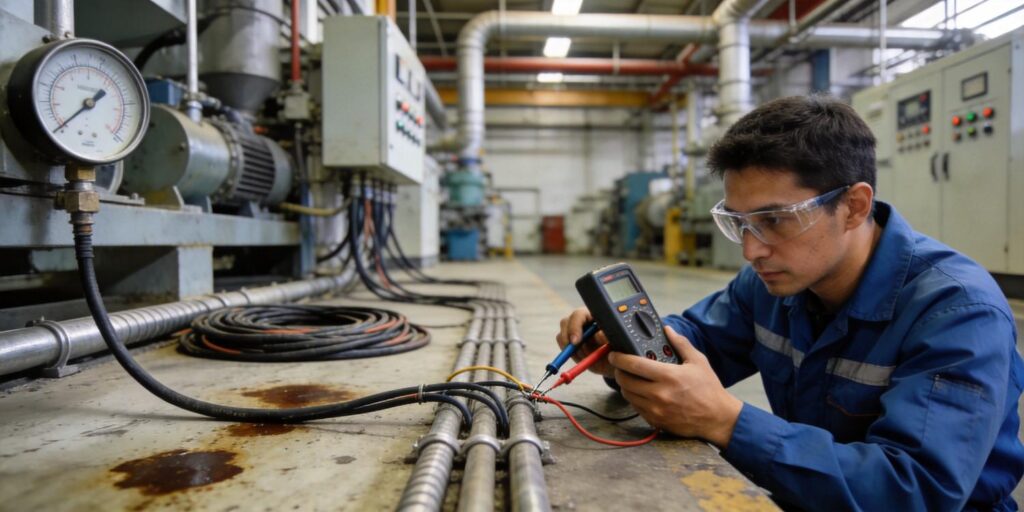
- Measure raw 0–10 V output at the transmitter with a battery-powered multimeter (eliminates ground-loop effects).
- Compare with a handheld oscilloscope to quantify noise amplitude and frequency.
- Power the gauge from an isolated lab supply; if noise disappears, the plant grounding or power rail is suspect.
- For the VG-SM225, verify high-voltage status LED and startup time; extended delays or flickering indicate contamination rather than EMI.
- Cross-check against a second gauge (Pirani + cold cathode) at the same port; agreement rules out process-related pressure fluctuations.
Poseidon transmitters store factory calibration constants in EEPROM; any sudden offset beyond ±5 % warrants electrode cleaning (cold cathode) or full replacement (Pirani filament). Digital RS232 output provides raw ADC counts for deeper diagnostics without analog intermediaries.
7. Preventive Installation Design
Noise prevention begins at the design stage. Specify Poseidon gauges with the following features for new or retrofit projects:
- Short cable runs (<10 m ideal) routed away from power cables (minimum 30 cm separation).
- Conduit or cable-tray shielding for runs longer than 15 m.
- Isolated power and signal terminals inside the control cabinet.
- Redundant digital output (RS232) as backup to analog for critical loops.
- Periodic firmware checks via RS232 to confirm compensation algorithms remain optimized.
The compact size of both models allows mounting closer to the chamber yet still outside high-EMI zones. Their built-in over-range protection and status indicators further reduce false trips caused by transient noise spikes.
8. Field Testing Checklist
Use this eight-step checklist during commissioning or after any noise-related incident:
- Verify cable shielding and single-end grounding continuity with a milliohmmeter (<1 Ω shield-to-ground).
- Confirm star-ground topology and absence of parallel ground paths.
- Install/test isolation amplifier or digital converter if ground potential difference >0.2 V.
- Apply RC filter and record noise reduction on oscilloscope.
- Run 30-minute stability test at base pressure with all plant equipment energized.
- Log both analog and digital outputs simultaneously; discrepancy >2 % indicates EMI coupling.
- Clean VG-SM225 electrodes if discharge current is unstable; replace VG-SP205 if filament resistance drifts.
- Document as-found/as-left readings, filter settings, and grounding changes for future reference.
Following this checklist typically resolves 90 % of reported noise issues within a single shift. Poseidon provides pre-configured PLC function blocks and sample filter code to accelerate implementation.
Signal noise in vacuum gauge installations is rarely a gauge defect—it is almost always an installation or environmental challenge. Poseidon Scientific’s VG-SP205 and VG-SM225 transmitters are engineered with industrial robustness in mind: internal compensation, low-impedance outputs, and optional digital protocols give users multiple paths to noise-free performance. By systematically addressing EMI sources, cabling, grounding, and filtering, plants achieve the stable, repeatable vacuum data required for modern process control—while enjoying the 60–70 % cost advantage over traditional OEM instrumentation.
References & Further Reading
Lafferty, J. M. (Ed.). (1998). Foundations of Vacuum Science and Technology. John Wiley & Sons.
Peacock, R. N., et al. (1991). “Comparison of hot cathode and cold cathode ionization gauges.” Journal of Vacuum Science & Technology A, 9(3), 1977.
Experiencing persistent signal noise with your vacuum gauges? Poseidon applications engineers offer free on-site noise audits, custom shielding recommendations, and plug-and-play filter kits. Contact us today to schedule a diagnostic visit and restore rock-solid pressure measurement to your industrial vacuum system.

