PVD Vacuum Stages: From Roughing to Deposition
Physical Vapor Deposition (PVD) processes—sputtering, evaporation, and cathodic arc—rely on controlled vacuum environments to achieve line-of-sight atom transport, minimize oxidation, and ensure dense, adherent films. Each stage imposes distinct vacuum demands that directly affect coating quality, deposition rate, and system uptime.
The typical PVD cycle includes:
- Load-lock and roughing: Wafers or substrates enter at atmosphere; roughing pumps reduce pressure to ~1–10 mbar in minutes to limit moisture and contaminants.
- High-vacuum pump-down: Turbomolecular or cryogenic pumps bring the main chamber to base pressure (typically 10⁻⁶–10⁻⁷ Torr) before process gas introduction. This step removes residual gases and establishes the low mean-free-path environment required for uniform film growth.
- Process vacuum: Argon (or reactive gases) is introduced to 1–10 mTorr for magnetron sputtering or lower for evaporation. Precise control here governs plasma density and stoichiometry.
- Cooldown and venting: Return to atmosphere under controlled conditions to prevent condensation or arcing.
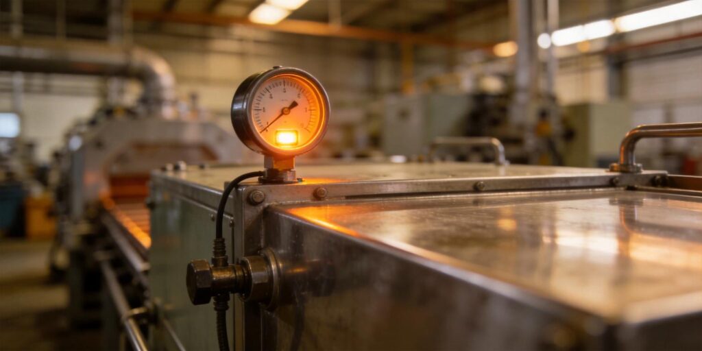
High-vacuum monitoring is critical during pump-down and base-pressure stabilization. Even brief excursions above target levels can introduce oxygen or water vapor that degrade film properties. Engineers therefore require gauges that deliver fast, repeatable readings across the full cycle—especially in the high-vacuum regime where most legacy instruments struggle.
Required Pressure Range for Reliable PVD Monitoring
PVD systems operate across four decades of pressure, but the high-vacuum portion (10⁻³ to 10⁻⁷ Torr) is where film quality is determined. Rough vacuum (atmosphere to 10⁻³ Torr) handles load-lock and initial pump-down; high vacuum governs the actual deposition environment.
| Stage | Typical Pressure | Critical Monitoring Need |
|---|---|---|
| Roughing / Load-Lock | Atm to 10⁻³ Torr | Fast response, moisture detection |
| High-Vacuum Pump-Down | 10⁻³ to 10⁻⁶ Torr | Base-pressure stability, leak detection |
| Process (Sputtering) | 1–10 mTorr | Plasma pressure control, repeatability |
| Base Vacuum (Pre-Deposition) | <10⁻⁶ Torr | Contamination control, ultimate vacuum verification |
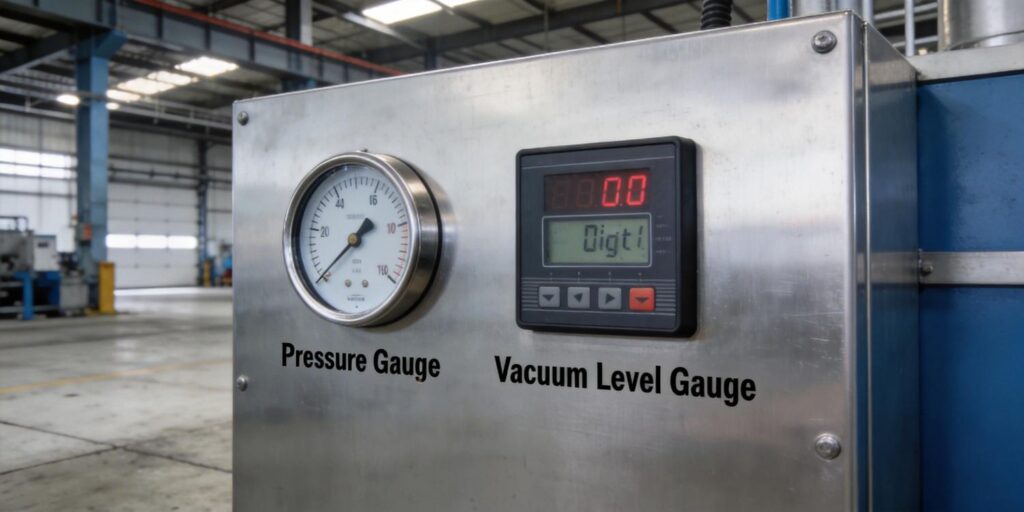
No single gauge covers this range optimally. Thermal-conductivity (Pirani) gauges lose sensitivity below 10⁻³ Torr, while cold-cathode ionization gauges cannot safely operate above that threshold without electrode damage. The proven solution used in modern PVD tools is a hybrid pair: the VG-SP205 Pirani Vacuum Transmitter for rough vacuum and the VG-SM225 Cold Cathode Vacuum Gauge for high vacuum. Overlap at 10⁻³ Torr enables automatic range switching in the PLC or tool controller, delivering continuous coverage from atmosphere to 10⁻⁷ Torr.
Gauge Placement: Maximizing Accuracy in PVD Chambers
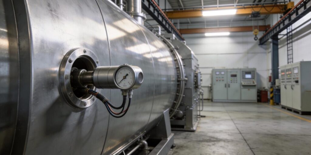
Gauge location dramatically affects reading fidelity. Installing on a long side-arm or pump foreline introduces conductance errors and lag, particularly during dynamic pump-down. Best practice is direct chamber-wall mounting via KF16 or KF25 flanges. This measures true cavity pressure—the value that actually influences plasma and film growth.
Additional placement guidelines for PVD systems:
- Position the high-vacuum gauge (VG-SM225) away from gas inlets and substrate heaters to avoid local pressure gradients.
- Use short, wide-bore extensions only when thermal isolation is required (e.g., near 300 °C pedestals).
- Orient the VG-SM225 magnet axis parallel to any electron or ion beams to minimize Lorentz-force interference.
- Maintain ≥20–30 cm separation from sensitive components; the compact positive-magnetron design (~100 Gauss) keeps stray fields localized.
- Install an isolation valve upstream for gauge removal during chamber cleaning without breaking main vacuum.
Both Poseidon transmitters support arbitrary orientation and share identical compact footprints, simplifying dual-gauge installations even in space-constrained cluster tools.
Monitoring Strategy: Real-Time Control and Data Integration
Effective PVD monitoring combines hardware, software, and interlocks for closed-loop control. The hybrid VG-SP205 + VG-SM225 setup feeds both 0–10 V analog and customizable RS232 digital outputs into the tool PLC. Analog provides instantaneous response for fast pump-down interlocks; digital delivers full diagnostics (sensor status, HV on/off, clean-recommended flag) and error-checked data for recipe logging.
Typical strategy:
- Below 10⁻³ Torr: Rely on the VG-SM225 cold cathode (software interlock disables its high voltage during roughing to protect electrodes).
- Above 10⁻³ Torr: Use the VG-SP205 Pirani for rapid, maintenance-free readings.
- Automatic range switching and averaging in the PLC smooth transitions and filter transients.
- Trend base pressure over multiple runs to detect leaks or contamination early.
Protocol customization—available from just 5–10 units—lets engineers define exact data frames, units, and status codes that match existing SCADA or MES systems. This eliminates driver development and ensures seamless integration with legacy tools or new Industry 4.0 platforms.
Reliability Improvement: Contamination Management and Long-Term Stability
PVD environments generate metal vapors, reactive gases, and sputtered material that coat gauge electrodes over time. The VG-SM225 addresses this with a fully removable sensor head: simply unscrew, abrade cathode and anode plates with 200–500 grit sandpaper until metallic luster returns, and reinstall—no chamber venting required. Restoration takes under 10 minutes and returns accuracy to factory levels in >95 % of cases.
Complementary reliability features include:
- Platinum filament in the VG-SP205 for corrosion resistance and 3–5 year maintenance-free life in rough vacuum.
- Built-in temperature compensation (15–50 °C) on both gauges to eliminate drift during thermal cycling.
- Over-pressure protection on the cold cathode that automatically disables high voltage above 10⁻³ Torr.
- Stainless-steel electrodes, PEEK insulators, and vacuum-grade seals delivering ≤10⁻¹¹ Pa·m³/s leak rate.
Field data from PVD and mass-spectrometer users show mean time between failures exceeding 40,000 hours when quarterly cleaning and hybrid monitoring are implemented. Compared with larger imported cold-cathode gauges, the VG-SM225’s compact positive-magnetron design reduces stray-field issues and installation complexity while cutting unit cost by 30–50 %.
Upgrade Your PVD Vacuum Monitoring Today
High-vacuum monitoring is the foundation of consistent, high-quality PVD coatings. The combination of the VG-SP205 Pirani Vacuum Transmitter for rough vacuum and the VG-SM225 Cold Cathode Vacuum Gauge for high vacuum delivers the pressure range, response speed, integration flexibility, and contamination tolerance that modern PVD systems demand—at a price point that supports both pilot lines and full production.
Compact footprints, field-cleanable sensors, customizable protocols, and shared RJ45 hardware make these transmitters the practical choice for engineers who need reliable data without the premium cost or maintenance burden of legacy imported instruments.
Contact the Poseidon Scientific applications engineering team today for a no-obligation consultation. Share your chamber geometry, dominant gases, PLC platform, and quantity, and receive a firm quotation, custom protocol sample, wiring diagram, and performance recommendation within 24 hours.
Explore full specifications and request an evaluation kit:
Optimize your PVD vacuum monitoring. Improve film quality. Reduce downtime. Your high-vacuum solution starts here.