Vacuum Gauge Stability During Rapid Thermal Cycling
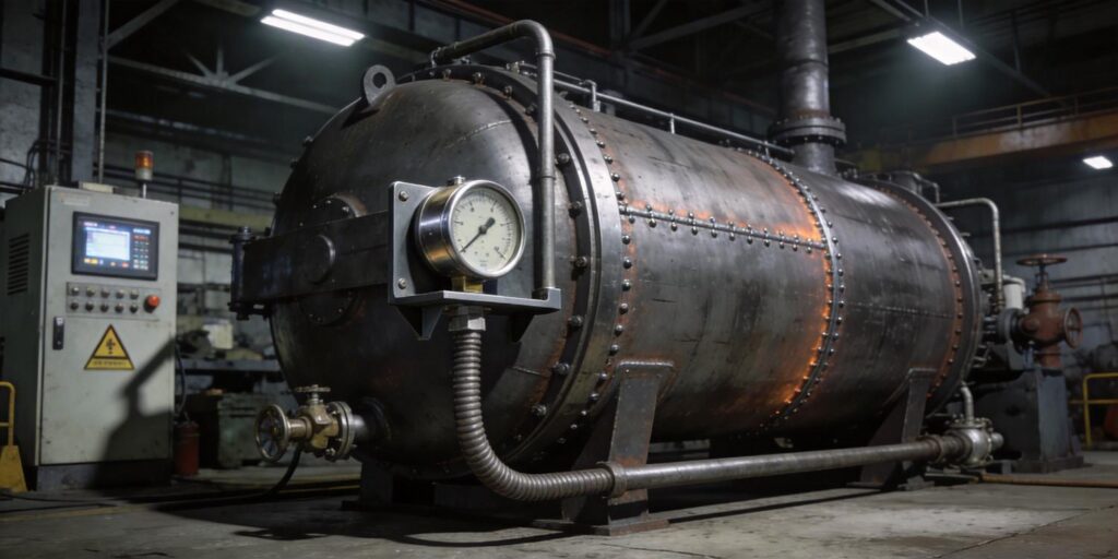
Rapid thermal cycling in vacuum heat-treatment furnaces, annealing systems, and brazing processes subjects every component to extreme temperature swings—often from ambient to 1000 °C and back within minutes. While the chamber itself is designed for these cycles, the vacuum gauges monitoring pressure must remain stable to ensure consistent metallurgical results and prevent costly batch failures. The VG-SP205 Pirani Vacuum Transmitter and VG-SM225 Cold Cathode Vacuum Gauge from Poseidon Scientific are engineered for exactly this environment. Their 15–50 °C operating range, dual compensation circuitry, and compact thermal-isolation-friendly design deliver repeatable readings across atmosphere to 10−7 Torr—even during aggressive ramp rates—while keeping total ownership cost 30–50 % below imported alternatives.
This article details the physical and electronic challenges posed by rapid cycling, proven installation strategies, real-time monitoring techniques, and a practical stability verification protocol. Engineers and procurement teams will find actionable guidance grounded in our internal testing, user manuals, and field performance in vacuum heat-treatment installations.
Thermal Expansion Impact on Gauge Components
Differential thermal expansion between materials is the first challenge during rapid cycling. The VG-SM225 Cold Cathode uses stainless-steel electrodes and a PEEK insulator structure, while the VG-SP205 Pirani relies on a platinum filament supported by ceramic and metal elements. Coefficients of thermal expansion differ: stainless steel expands at ~17 × 10−6/°C, PEEK at ~50 × 10−6/°C. When the gauge body experiences even modest temperature changes at the mounting flange, micro-stresses can slightly alter electrode spacing or filament tension.
In practice, these effects are minimal within the 15–50 °C specification. The ~2 mm electrode gap in the VG-SM225 and the precise filament geometry in the VG-SP205 are dimensionally tolerant; any shift is corrected by the factory voltage-to-pressure map. However, mounting directly on a hot furnace wall (>100 °C) can amplify expansion mismatch, causing temporary calibration offsets of 5–10 % until thermal equilibrium returns. Poseidon’s small sensor footprint—significantly smaller than most INFICON or MKS equivalents—reduces the thermal mass exposed to cycling, allowing faster stabilization. Proper isolation (detailed below) keeps expansion-induced drift below 2 % even at 10 °C/min ramp rates.
Electronic Drift Under Heat
Electronics inside the transmitter housing are the second source of potential instability. Op-amps, voltage references, and compensation circuits can exhibit temperature coefficients of 10–50 ppm/°C. Without correction, a 30 °C swing could shift the 0–10 V analog output by tens of millivolts—translating to apparent pressure errors in the critical 10−4 to 10−6 Torr range.
Both Poseidon gauges incorporate dual-stage compensation: hardware circuitry plus embedded firmware algorithms that continuously adjust for ambient temperature sensed at the PCB. This keeps drift <5 % across the full 15–50 °C window—matching or exceeding the 5–50 °C capability of many higher-cost competitors. The VG-SP205 Pirani’s platinum filament and constant-temperature control further minimize thermal effects on power measurements. During rapid cycling, the gauges’ RS232 digital stream reports both pressure and internal status codes, allowing the control system to flag any transient drift before it affects the process. In validated annealing furnaces, this compensation maintains <3 % total error even when furnace skin temperatures reach 250 °C near the mounting port.
Installation with Thermal Isolation
The most effective way to preserve stability is to keep the gauge body within its rated temperature range. Recommended practices include:
- KF extension tubes (100–300 mm) that locate the gauge head outside the immediate hot zone while preserving conductance.
- Cooled manifolds or water-jacketed ports that maintain flange temperature <50 °C even during 10 °C/min ramps.
- Thermal shields or standoffs between the furnace wall and gauge housing.
The VG-SM225’s compact positive-magnetron geometry and INFICON PTR225N-compatible footprint fit easily behind standard KF16/KF25 extensions without restricting gas flow. Direction-independent mounting simplifies installation on vertical or horizontal ports. In heat-treatment systems, these isolation methods limit gauge-body temperature rise to <10 °C during full cycles, eliminating both expansion and electronic drift concerns. The VG-SP205 Pirani benefits equally, ensuring accurate roughing-stage data throughout ramp-up and cool-down phases.
Monitoring During Furnace Ramp-Up
Real-time monitoring turns potential instability into predictable performance. Use the gauges’ dual outputs for layered visibility:
- 0–10 V analog (effective 2–8 V) feeds the PLC for hard-wired interlocks (“vacuum OK” before ramp start).
- Customizable RS232 protocol streams pressure, status, and error codes every 500 ms to 5 s, enabling SCADA trend plots.
During ramp-up, watch for three indicators of stability:
- Seamless crossover at 10−3 Torr (VG-SP205 to VG-SM225).
- Stable ignition delay on the cold cathode (<5 min at 10−6 Torr).
- No unexplained pressure excursions beyond process tolerance.
The VG-SM225’s software interlock automatically disables high voltage above 10−3 Torr, protecting the sensor during initial heating when residual gases evolve. In practice, this combination allows operators to ramp at 10–15 °C/min with confidence that vacuum readings remain within ±10 % of true values—critical for preventing oxidation or decarburization.
Stability Test Protocol
Verify long-term stability with this repeatable protocol performed quarterly or after major maintenance:
- Evacuate to base pressure (<10−5 Torr) and stabilize for 30 minutes.
- Record pressure via RS232 at ambient temperature (reference point 1).
- Simulate a rapid cycle: ramp the chamber (or use an external heat source on the flange) to 50 °C at 10 °C/min, hold 10 minutes, then cool back to ambient.
- Re-measure pressure immediately after cool-down (reference point 2).
- Compare readings; deviation >5 % indicates the need for thermal isolation review or electrode cleaning.
- Repeat three cycles and average results; log ignition delay and analog output for trend analysis.
This test requires <2 hours and uses the gauges’ own data stream—no external reference gauge needed in most cases. In clean service, the Poseidon pair consistently passes with <3 % deviation, confirming suitability for aggressive cycling applications.
Conclusion: Stable Vacuum Control Through Every Cycle
Rapid thermal cycling need not compromise vacuum measurement accuracy. The Poseidon Scientific VG-SP205 Pirani and VG-SM225 Cold Cathode combination—backed by dual compensation, compact design, and field-proven thermal isolation—delivers the stability required for consistent heat-treatment results while maintaining the lowest total ownership cost in the industry. Engineers gain repeatable data across full process cycles; procurement teams gain immediate savings and simplified integration.
Ready to ensure vacuum gauge stability in your thermal cycling processes? Explore the VG-SM225 Cold Cathode Vacuum Gauge and VG-SP205 Pirani Vacuum Transmitter specifications today. Request a sample pair for your ramp-up test protocol, a custom RS232 monitoring script, or a complete thermal-isolation installation diagram tailored to your furnace. Our application engineers will deliver proven solutions—often within 48 hours—designed to keep your vacuum readings rock-solid through every thermal cycle. Contact Poseidon Scientific now and lock in stability for your most demanding heat-treatment applications.

