
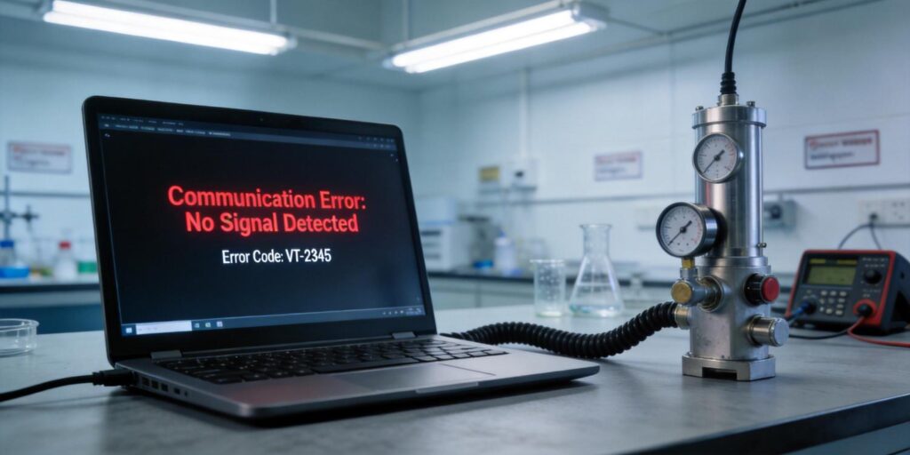
In high-vacuum systems such as mass spectrometers, scanning electron microscopes, and vacuum heat-treatment furnaces, precise pressure data must reach the control system without interruption. Poseidon Scientific’s VG-SP205 Pirani Vacuum Transmitter and VG-SM225 Cold Cathode Vacuum Gauge deliver both analog (0–10 V) and digital RS232 outputs, giving engineers flexible integration options. When digital communication is chosen, reliable frame transmission becomes essential. Transmission errors can trigger false alarms, interrupt data logging, or cause process downtime. This guide examines the RS232 frame structure used in our transmitters, the most frequent error types, cable-length constraints, noise-immunity practices, and a systematic diagnostic workflow—practical information engineers and procurement teams rely on to keep vacuum processes running smoothly.
RS232 Frame Structure in Poseidon Vacuum Transmitters
Both the VG-SP205 (atmosphere to 10⁻³ Torr) and VG-SM225 (10⁻³ to 10⁻⁷ Torr) support RS232 at the default settings of 9600 baud, 8 data bits, 1 stop bit, no parity. The protocol is full-duplex and point-to-point, with a fixed 9-byte output frame transmitted every approximately 100 ms. The frame is intentionally compact and includes built-in status, error, and checksum fields for maximum robustness in industrial environments.
The output data frame format is structured as follows:
| Byte | Function | Value / Range | Notes |
|---|---|---|---|
| 0 | Data frame length | 7 | Fixed payload indicator |
| 1 | Pages / command echo | 5 | Fixed identifier |
| 2 | Status codes | 0–255 | Bit 4 & Bit 5 encode pressure unit |
| 3 | Error code | 0–255 | See error-code table below |
| 4 | High byte of measurement value | 0–255 | Combined with byte 5 for pressure |
| 5 | Low byte of measurement value | 0–255 | Combined with byte 4 for pressure |
| 6 | Software version number | 0–255 | Version = value / 10 |
| 7 | Sensor type & check | 10 | Fixed sensor identifier |
| 8 | Checksum / reserved | 0–255 | Integrity verification |
Status byte (byte 2) uses bits 4 and 5 to indicate the active pressure unit:
- Bit 5 = 0, Bit 4 = 0 → mbar
- Bit 5 = 0, Bit 4 = 1 → Torr (factory default)
- Bit 5 = 1, Bit 4 = 0 → Pa
Pressure is encoded logarithmically for wide dynamic range. The host calculates the value from bytes 4 and 5 using the formula appropriate for the unit reported in byte 2:
\( P_{\text{mbar}} = 10^{((high \times 256 + low)/4000 – 12.5)} \)
\( P_{\text{Torr}} = 10^{((high \times 256 + low)/4000 – 12.625)} \)
\( P_{\text{Pa}} = 10^{((high \times 256 + low)/4000 – 10.5)} \)
This structure—compact, self-describing, and protected by an integrity byte—ensures that even in electrically noisy vacuum chambers the host can verify data validity before acting on it.
Common Transmission Errors
Most communication problems fall into four categories, each with clear symptoms in the Poseidon frame:
- Framing errors – Occur when the stop bit is missing or corrupted, usually from baud-rate mismatch or cable capacitance. The receiver discards the frame; our 100 ms interval gives the host time to detect and request a retry if the protocol layer is customized.
- Checksum / integrity failures – Byte 8 fails validation. Caused by EMI, poor grounding, or marginal cable. The transmitter still sends the next frame 100 ms later; the host simply discards the corrupt packet and logs the event.
- Overrun errors – Rare at 9600 baud and 9 bytes, but possible if the host’s serial buffer is not read promptly. Our low data rate (90 bytes/s) leaves generous margin for PLC scan cycles.
- Sensor-specific error codes (byte 3) – These are not transmission errors but sensor-health flags:
- Binary 1000 (decimal 128) → Cold-cathode discharge failure (VG-SM225)
- Binary 1001 (decimal 129) → Pirani filament or bridge failure (VG-SP205)
These codes allow the control system to distinguish between communication faults and genuine gauge problems, a feature appreciated in 24/7 production environments.
Because the protocol layer is fully customizable for orders of five units or more, customers can add application-specific error handling or switch to Modbus-like addressing without hardware changes.
Cable Length Limits
RS232 is an unbalanced, single-ended interface. The EIA/TIA-232 standard recommends a maximum cable length of 15 m (50 ft) at 9600 baud with typical 50 pF/m capacitance. In practice, vacuum-system integrators achieve the best reliability with the following guidelines:
- Recommended: ≤ 10 m shielded cable for both VG-SP205 and VG-SM225
- Maximum reliable: 15 m when using low-capacitance, twisted-pair cable (e.g., Belden 9841)
- Beyond 15 m: signal rise-time degradation increases framing errors; consider RS422/485 conversion (pre-reserved on our PCB for future board spins)
Longer runs are occasionally requested for large coating chambers. In such cases we advise adding a simple RS232 repeater or switching to our customizable digital protocol with higher drive strength.
Noise Immunity Best Practices
Vacuum systems are electrically hostile environments—turbo pumps, RF plasma generators, and stepper motors produce both conducted and radiated EMI. Our transmitters incorporate several design features for robustness, but field installation still matters:
- Use shielded, twisted-pair cable with the shield connected to chassis ground at one end only (avoid ground loops).
- Route RS232 cables at least 30 cm from motor power lines and high-voltage feedthroughs.
- Add ferrite beads on both ends if EMI from nearby RF sources is suspected.
- Ensure the RJ45 or DB9 connector housing is metal and bonded to the vacuum-chamber ground plane.
The 9-byte frame with explicit checksum and status byte provides a second layer of protection: corrupted frames are silently discarded, and the next valid frame arrives within 100 ms. This combination of hardware shielding and protocol-level integrity keeps false pressure readings to a minimum even in semiconductor or PVD tool clusters.
Diagnostic Approach
When communication appears erratic, follow this sequence—typically resolved within minutes:
- Verify physical connections: TX (PIN1) to host RX, RX (PIN3) to host TX, GND (PIN7/8) common. Confirm +5 V power on PIN4 if using the optional power pin.
- Confirm host serial settings exactly match 9600-8-N-1. Mismatch is the most common cause of framing errors.
- Open a terminal emulator (Tera Term, PuTTY, or your PLC serial monitor) and capture raw hex bytes. Look for the repeating pattern starting with 0x07, 0x05.
- Validate the frame:
- Byte 0 = 7 and byte 1 = 5
- Byte 7 = 10 (sensor type)
- Checksum byte 8 matches your implementation
- Parse byte 2 for unit and byte 3 for error codes. A non-zero error code immediately identifies whether the issue is sensor-related (cold-cathode start failure or Pirani filament open) rather than wiring.
- If frames are missing entirely, check cable length and shielding. Swap with a known-good 3 m cable to isolate.
- For persistent issues, request our free protocol-customization worksheet; we can add CRC-16, heartbeat bytes, or Modbus RTU mapping in 2–3 weeks for qualifying orders.
Our built-in status and error fields make remote diagnostics straightforward—many customers log byte 3 directly into their SCADA system for predictive maintenance alerts.
Ensuring Reliable Digital Vacuum Measurement
The RS232 interface on the VG-SP205 Pirani Vacuum Transmitter and VG-SM225 Cold Cathode Vacuum Gauge is engineered for the real-world demands of analytical instruments and industrial vacuum systems. With a compact 9-byte frame, unit-aware status bits, sensor-health error codes, and a 100 ms update rate, the protocol delivers the reliability engineers expect while keeping cost and size low.
Whether you are retrofitting an existing mass spectrometer, specifying gauges for a new vacuum furnace line, or scaling a semiconductor tool fleet, our transmitters give you the digital confidence you need.
Explore the VG-SP205 Pirani Vacuum Transmitter or the VG-SM225 Cold Cathode Vacuum Gauge today. Need a custom protocol variant, longer cable support, or help diagnosing an existing installation? Our applications team is ready to assist—contact us directly and let’s keep your vacuum data flowing accurately and reliably.


