Understanding the Pressure Rise Test for Micro Leak Detection
In vacuum systems, even micro leaks measuring 10⁻⁹ Torr·L/s or smaller can compromise process integrity, introduce contamination, or reduce equipment lifetime. The pressure rise test (also called rate-of-rise or isolation test) provides a simple, reliable, and gauge-based method to quantify these leaks without specialized helium mass spectrometers. By isolating the chamber from pumps and observing the rate at which pressure increases, engineers can calculate the total gas load entering the volume and distinguish real leaks from virtual ones.
This technique is widely used in aerospace brazing furnaces, mass spectrometer chambers, semiconductor tools, and vacuum heat-treatment systems. It requires only accurate vacuum gauges, a known chamber volume, and disciplined data collection. When performed correctly with complementary Pirani and cold cathode gauges, it delivers quantitative leak rates that meet NADCAP, AS9100, and OEM specifications.
Isolating the Chamber: Essential Steps for Reliable Results
Accurate pressure rise data begins with complete isolation of the test volume from all pumping and gas sources. Close all valves between the chamber and roughing/turbo pumps, forelines, and any process gas inlets. Ensure the isolation valves themselves are leak-tight—double-valve arrangements or blanked flanges are recommended for critical applications.
Before isolation, pump the system to a base pressure at least one decade below the expected test range (typically 10⁻⁵ Torr or lower for micro-leak detection). Allow the system to stabilize for 10–30 minutes to minimize transient outgassing. Record the starting pressure, chamber temperature, and gauge identity. Temperature control is critical: maintain the environment within 15–50 °C to avoid gauge drift that could mask or exaggerate the rise.
In production environments, many users isolate only the process chamber while keeping foreline gauges active for cross-verification. Poseidon Scientific’s VG-SP205 Pirani Vacuum Transmitter and VG-SM225 Cold Cathode Vacuum Gauge support this workflow with their compact KF16/KF25 flange options and arbitrary mounting orientation, ensuring minimal conductance loss during isolation.
Measuring the Rate of Rise: From Raw Data to Leak Rate Calculation
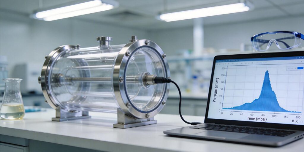
Once isolated, record pressure at regular intervals—every 10–60 seconds for the first 5–10 minutes, then every 5 minutes for longer tests (up to 1 hour for very tight systems). Plot pressure versus time; a linear slope indicates a dominant real leak, while a decreasing slope points to desorption.
The fundamental equation for leak rate Q (in Torr·L/s) is:
Q = V × (ΔP / Δt)
where V is the isolated volume in liters, ΔP is the pressure change in Torr, and Δt is the time interval in seconds. Convert units as needed (1 Pa·m³/s ≈ 7.5 Torr·L/s). For example, a 50 L chamber showing a 2 × 10⁻⁶ Torr rise over 600 s yields Q ≈ 1.7 × 10⁻⁷ Torr·L/s.
Modern transmitters simplify this process. The VG-SP205 and VG-SM225 provide both 0–10 V analog output (linear in the effective range) and customizable RS232 digital protocols, allowing direct integration into data loggers or PLCs for automated slope calculation and real-time alerts.
Distinguishing Real Leaks from Desorption (Virtual Leaks)
Not every pressure rise signals a leak. Virtual leaks—adsorbed gases, trapped volumes in welds, or surface porosity—produce an initial rapid rise that slows exponentially as desorption depletes the reservoir. Real leaks from seals, cracks, or permeation maintain a constant rate proportional to the pressure differential.
Practical differentiation methods include:
- Repeat the test after a brief pump-down and re-isolation. Desorption rates decrease on successive cycles; real leaks remain constant.
- Extended monitoring: after 30–60 minutes, desorption contributions typically drop below 10% of the initial rate.
- Temperature cycling: gentle heating (50–80 °C) accelerates desorption without affecting true leak rates significantly.
- Gauge location: mount the gauge directly on the chamber wall to minimize conductance errors between the measurement point and potential leak sites.
The VG-SM225’s cleanable Penning cell design is particularly useful here: electrode contamination can mimic desorption, but quick sanding restores baseline performance without breaking vacuum seals.
Selecting the Right Gauge: Pirani vs. Cold Cathode for Leak Detection
Effective micro-leak detection spans multiple pressure decades, making a single gauge insufficient. The VG-SP205 Pirani Vacuum Transmitter excels in the rough-to-medium vacuum range (atmosphere to 10⁻³ Torr), where initial pump-down and large leaks are most visible. Its platinum filament provides fast response (<1 s) and robust thermal conductivity measurement, ideal for detecting gross leaks during isolation setup.
For true micro leaks at high vacuum (10⁻³ to 10⁻⁷ Torr), the VG-SM225 Cold Cathode Vacuum Gauge is the superior choice. Its Penning discharge principle offers high sensitivity to small ion currents, with minimal X-ray limitations compared to hot-cathode alternatives. The positive magnetron geometry and removable electrodes enable in-situ cleaning, extending service life in production environments where occasional contamination occurs.
Best practice: use both gauges in tandem. The Pirani monitors the transition region and confirms isolation integrity; the cold cathode provides the high-resolution data needed for sub-10⁻⁸ Torr·L/s leaks. Their combined range eliminates blind spots, and customizable RS232 protocols allow simultaneous logging on a single interface. Operating both within 15–50 °C with built-in compensation ensures the data remain trustworthy throughout the test.
Data Recording and Analysis Tips for Maximum Accuracy
High-quality data turns a qualitative test into a quantitative specification tool. Use digital outputs rather than analog whenever possible—RS232 eliminates A/D conversion noise and enables timestamped logging at 1 Hz or better. Apply a short digital filter (0.5–2 s time constant) to suppress electrical noise without distorting the rise slope.
Record chamber temperature, gauge identity, and calibration date alongside pressure. Export data in CSV format for spreadsheet analysis or import directly into SPC software for trend tracking. For critical systems, perform the test under production-like thermal conditions to capture temperature-dependent leak behavior.
Maintenance note: the VG-SM225 requires only periodic electrode polishing (500-mesh sandpaper) if startup delays or low readings appear—restoring full sensitivity in minutes. The VG-SP205 is essentially maintenance-free for 3–5 years in clean service.
Acceptance Criteria Example: Industry Benchmarks
Leak rate limits vary by application. In aerospace vacuum brazing of turbine components, typical acceptance is <5 × 10⁻⁹ Torr·L/s after 30-minute isolation at 10⁻⁵ Torr base pressure. Semiconductor PVD chambers often require <1 × 10⁻⁹ Torr·L/s to prevent process gas contamination. General industrial vacuum furnaces accept up to 1 × 10⁻⁷ Torr·L/s for non-critical heat treatment.
Always document the test volume, starting pressure, temperature, and gauge type in the quality record. If the calculated rate exceeds the limit, perform helium leak detection for localization. Poseidon gauges ship with traceable factory calibration certificates, supporting audit requirements under AMS 2750 and NADCAP AC7102.
Conclusion: Integrate Gauge-Based Leak Detection into Your Standard Operating Procedure
The pressure rise test, when executed with accurate, full-range vacuum gauges, offers a cost-effective, in-house method for detecting and quantifying micro leaks before they impact production. By pairing the VG-SP205 Pirani for rough vacuum oversight with the VG-SM225 Cold Cathode for high-vacuum precision, engineers achieve complete coverage, rapid troubleshooting, and defensible data for quality compliance.
These Poseidon Scientific transmitters deliver the durability, compactness, and protocol flexibility that modern vacuum systems demand—at a fraction of imported sensor costs—while supporting easy electrode maintenance on the cold cathode unit.
Learn more about the VG-SP205 Pirani Vacuum Transmitter or explore the VG-SM225 Cold Cathode Vacuum Gauge.
Need a step-by-step leak test guide tailored to your chamber volume and process? Contact our applications team for a no-obligation vacuum system audit. We’ll provide customized test procedures, recommended gauge placement, and protocol settings to help you detect micro leaks faster and with greater confidence.

