In vacuum systems for mass spectrometry, thin-film deposition, vacuum metallurgy, and pharmaceutical lyophilization, the pressure signal from your gauge is the single most important input to the control system. When that signal enters an error state—whether from sensor failure, over-range pressure, or communication dropout—the entire process can halt, waste batches, or trigger costly safety interlocks. Poseidon Scientific’s VG-SP205 Pirani Vacuum Transmitter and VG-SM225 Cold Cathode Vacuum Gauge are engineered with clear, unambiguous error signaling on both analog and digital outputs, giving engineers and procurement teams predictable behavior and fast diagnostics.
This article explains exactly what the “error signal voltage” means on the 0–10 V analog output, how each gauge behaves when pressure moves outside its rated range, recommended system-response strategies, PLC alarm configuration, and a step-by-step diagnostic workflow. The information is drawn directly from the transmitters’ design specifications and field-validated behavior, ensuring you can integrate these gauges with confidence and minimize unplanned downtime.
Define Error Signal Voltage
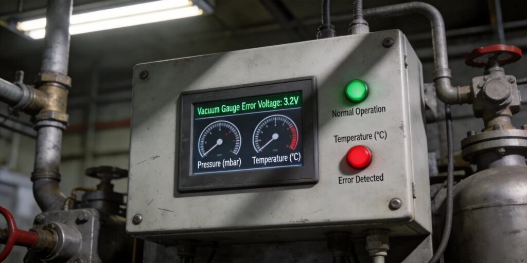
The VG-SP205 and VG-SM225 use a 0–10 V analog output scaled so the linear, usable measurement range falls between 2 V and 8 V. This deliberate 2–8 V “valid window” leaves the bottom 0–2 V and top 8–10 V ranges free for explicit error and out-of-range signaling—standard practice in industrial transmitters and immediately recognizable by any PLC or data-acquisition card.
Specifically:
- 0.0–1.9 V: Under-range or sensor-failure error (e.g., Pirani filament open, cold-cathode discharge failure, or power-supply fault).
- 2.0–8.0 V: Valid pressure measurement (linear and temperature-compensated).
- 8.1–10.0 V: Over-range condition (pressure above the gauge’s rated upper limit).
On the digital RS232 side, the same conditions are reported more granularly in byte 3 of the 9-byte frame (error code 0–255). Common values include:
| Error Code (decimal) | Meaning | Gauge Affected |
|---|---|---|
| 128 | Discharge failure / high-voltage disabled | VG-SM225 only |
| 129 | Filament open or bridge failure | VG-SP205 only |
| 130–255 | Reserved for future diagnostics | Both |
The analog error voltages and digital error codes are synchronized: if the digital frame reports code 128 or 129, the analog output will sit at 0–1.9 V within <100 ms. This dual-signal consistency lets you use analog for fast PLC loops and digital for detailed SCADA logging or IIoT dashboards.
Out-of-Range Behavior
Each gauge has clearly defined operating limits; exceeding them triggers predictable, safe behavior rather than erratic readings.
VG-SP205 Pirani Vacuum Transmitter
- Upper limit (atmosphere): Output rises smoothly to ~9.5–10 V. No damage occurs; the platinum filament simply reaches its maximum power limit.
- Lower limit (10⁻³ Torr): Output falls toward 2 V and eventually into the 0–1.9 V error band as resolution is lost. The gauge continues to report but with increasing uncertainty—exactly as thermal-conductivity physics predicts.
VG-SM225 Cold Cathode Vacuum Gauge
- Upper limit (>10⁻³ Torr): Firmware instantly disables the –2000 V supply to prevent sputtering and carbon buildup. The analog output drops to the 0–1.9 V error band and the red status LED flashes. The gauge remains powered and ready; it automatically re-enables when pressure returns below the safe threshold.
- Lower limit (10⁻⁷ Torr): Output approaches ~2.0 V. Ignition may take 15–30 minutes (normal physics), but once established the reading remains stable. No error voltage is asserted unless the discharge fails entirely.
Because the two gauges overlap at 10⁻³ Torr, the system always has at least one valid signal during pump-down and venting. The VG-SM225’s automatic high-voltage protection is especially valuable in research or production environments where operators (or students) may accidentally vent while the gauge is active.
System Response Strategy
Well-designed vacuum systems treat error voltages as actionable events rather than mere alarms. Recommended strategies include:
- Immediate safe-state: When either gauge drops to 0–1.9 V, the PLC should close high-vacuum valves, disable heaters or sources, and pause the process recipe. This prevents damage from operating blind.
- Dual-gauge voting: Require both gauges to agree on a valid 2–8 V reading before allowing critical steps (e.g., substrate heating or target ignition). Disagreement in the 10⁻³ Torr overlap zone triggers a soft alarm rather than full shutdown.
- Graceful degradation: In non-critical monitoring applications, continue using the remaining healthy gauge while logging the error for later review. The digital error code tells you exactly which sensor failed.
- Automatic retry for cold cathode: After a discharge-failure error, the VG-SM225 firmware will attempt re-ignition every 30 seconds once pressure falls below 10⁻³ Torr—no PLC intervention required.
These strategies are easily implemented because both transmitters share identical output scaling and update rates. Many customers request a one-time firmware customization (free for 5+ units) that adds a dedicated “system healthy” bit, further simplifying ladder logic.
PLC Alarm Setup
Configuring alarms takes minutes and dramatically improves response time. Typical ladder-logic or structured-text examples:
Analog (0–10 V) Alarm
IF (Gauge1_Voltage < 2.0 OR Gauge1_Voltage > 8.0) THEN
    Set Alarm_Bit := TRUE;
    Trigger_Process_Pause;
END_IF
Digital RS232 Alarm (preferred for diagnostics)
IF (Error_Code = 128) THEN  // Cold-cathode discharge failure
    Set ColdCathode_Fault := TRUE;
    Send_Maintenance_Notification;
ELSIF (Error_Code = 129) THEN  // Pirani filament failure
    Set Pirani_Fault := TRUE;
END_IF
Most modern PLCs (Siemens S7, Allen-Bradley Logix, Omron) can parse the 9-byte RS232 frame directly or via a simple serial module. Use the status byte (byte 2) to confirm pressure units and the checksum (byte 8) to discard corrupted frames before acting on any alarm. This combination of analog speed and digital intelligence gives you the best of both worlds.
Diagnostic Steps
When an error voltage or code appears, follow this 5-minute workflow:
- Check analog voltage first with a multimeter or PLC HMI. Confirm it is outside 2–8 V and note whether it is low (0–1.9 V) or high (8.1–10 V).
- Open a terminal emulator (Tera Term, PuTTY) on the RS232 line and capture raw hex. Verify byte 0 = 7, byte 1 = 5, and read byte 3 (error code) and byte 2 (status).
- Interpret the error code:
- 128 → VG-SM225 high-voltage disabled (pressure too high or contamination).
- 129 → VG-SP205 filament open (end of life or wiring fault).
- Cross-check the companion gauge: The overlapping range at 10⁻³ Torr means one sensor is usually still valid. Use its reading to confirm whether the fault is real or sensor-specific.
- Apply quick fixes:
- For VG-SM225 error 128: verify pressure < 10⁻³ Torr, then clean electrodes if needed (15-minute field procedure).
- For VG-SP205 error 129: replace the sensor head (plug-and-play).
Record the error code, timestamp, and chamber pressure in your maintenance log. The built-in software-version byte (byte 6) also helps confirm firmware compatibility after any updates.
Master Error Handling for Reliable Vacuum Control
The VG-SP205 Pirani Vacuum Transmitter and VG-SM225 Cold Cathode Vacuum Gauge turn potential sensor failures into clear, actionable signals—0–1.9 V or 8.1–10 V on analog, precise error codes on digital—giving your control system everything it needs to respond safely and intelligently. With identical footprints, shared interfaces, and free protocol customization, these transmitters integrate into any PLC or SCADA environment without custom hardware or lengthy validation cycles.
Whether you are designing a new research chamber, scaling a production coating line, or retrofitting legacy equipment, understanding and configuring these error ranges protects your process, your product, and your uptime.
Explore the VG-SP205 Pirani Vacuum Transmitter and VG-SM225 Cold Cathode Vacuum Gauge today. Need a ready-to-use PLC function block for error handling, sample LabVIEW error-parsing VI, custom firmware with expanded alarm bits, or a no-obligation dual-gauge sample kit with pre-wired test cables? Contact our applications team directly—we respond within 24 hours and have helped OEMs, research labs, and production facilities worldwide implement bullet-proof error strategies with zero commissioning surprises.

