
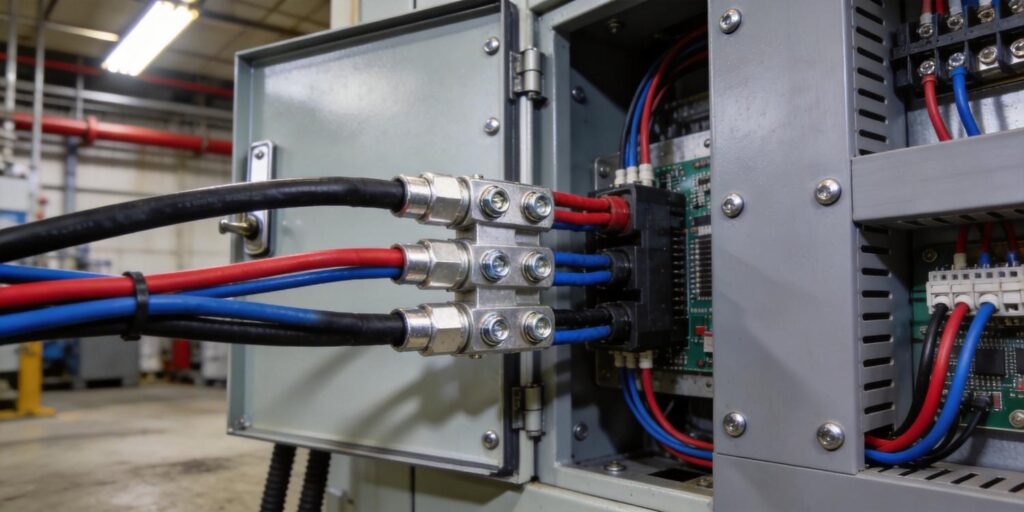
Signal Types Overview: Analog and Digital Outputs in Vacuum Gauges
In vacuum process control—whether for semiconductor etch, PVD thin-film deposition, mass spectrometry, or vacuum heat treatment—reliable pressure data must reach the PLC or SCADA system without distortion or delay. Vacuum gauges therefore offer two primary signal architectures: analog (continuous voltage or current) and digital (serial communication). Understanding the strengths and limitations of each helps engineers and procurement teams select the right transmitter for their tool architecture and cable runs.
Both the Poseidon Scientific VG-SP205 Pirani Vacuum Transmitter and VG-SM225 Cold Cathode Vacuum Gauge ship with native 0–10 V analog output and RS232 digital output as standard. RS485 is available via minor PCB revision for multi-drop networks, while 4–20 mA loops can be implemented with an external voltage-to-current converter when required by plant standards. This flexible portfolio lets users match the gauge output to existing control infrastructure without custom hardware or software rework.
0–10 V vs. 4–20 mA: A Direct Comparison
The two most common analog signals differ in noise performance, wiring simplicity, and diagnostic capability. The table below summarizes the practical differences for vacuum-gauge applications.
| Characteristic | 0–10 V | 4–20 mA |
|---|---|---|
| Signal span | 0–10 V (linear 2–8 V for both Poseidon gauges) | 4 mA = low scale, 20 mA = full scale |
| Wiring | Two-wire (signal + ground) plus power | Two-wire loop-powered (simpler long runs) |
| Noise immunity | Moderate; susceptible to ground loops and EMI | High; current loop rejects voltage drops and induced noise |
| PLC input compatibility | Direct to voltage ADC modules (most common) | Requires current-input modules or external shunt |
| Live-zero diagnostics | None (0 V can mean “no power” or “zero pressure”) | Built-in (4 mA = transmitter powered and healthy) |
| Cable length limit (unshielded) | ~10–15 m before noise becomes significant | Up to 1000 m with proper shielding |
| Power consumption impact | Negligible on gauge side | Loop-powered transmitters draw slightly more |
For most vacuum tools with cable runs under 20 m, the 0–10 V output of the VG-SP205 and VG-SM225 is the simplest and most cost-effective choice. It maps directly to the 2–8 V linear range used by both gauges, delivering pressure readings with no scaling required in the PLC. In legacy plants that standardize on 4–20 mA, an inexpensive external converter preserves the native 0–10 V signal while satisfying the current-loop requirement.
Noise Immunity in Industrial Environments
Fab and process floors are electrically noisy environments. RF generators, stepper motors, and high-voltage plasma supplies can induce voltages that corrupt low-level signals. The 4–20 mA current loop excels here because the receiver measures current, not voltage; any induced voltage drop along the cable is rejected as long as the loop supply can maintain compliance voltage.
The 0–10 V signal, while simpler, requires careful shielding and single-point grounding to minimize common-mode noise. Poseidon gauges incorporate internal filtering and temperature-compensated circuitry that keeps output ripple below 10 mV even in the presence of nearby RF sources. For runs longer than 15 m, engineers should use twisted-pair shielded cable with the shield grounded at the PLC end only. In practice, the 0–10 V output of both Poseidon transmitters has proven robust in side-by-side testing against 4–20 mA competitors, provided standard industrial wiring practices are followed.
PLC Integration Tips
Modern PLCs make integration straightforward. For analog 0–10 V:
- Wire the gauge output directly to a voltage-input channel (AI0 for Pirani, AI1 for cold cathode in dual-gauge setups).
- Scale the 2–8 V range to engineering units (pressure in mbar or Torr) using the PLC’s built-in linear scaling block—no custom code required.
- Use the overlap zone (≈10-3 mbar) for cross-validation between Pirani and cold-cathode readings.
For digital RS232:
- Connect TX/RX/GND to a serial port or Ethernet gateway.
- Request custom protocol matching during ordering (5–10 unit minimum); Poseidon can emulate legacy gauge command sets to eliminate software changes.
- Access diagnostic bytes for filament health, high-voltage status, and error codes—information unavailable from analog signals alone.
RS485 multi-drop capability (via PCB revision) allows up to 32 gauges on a single bus, simplifying large tool clusters. In all cases, the RJ45 connector on both Poseidon gauges reduces field wiring time; DB9 or DB15 adapters are available for older control cabinets.
Long Cable Installation Practices
Cable runs exceeding 20 m are common in cluster tools and multi-chamber platforms. Follow these guidelines to preserve signal integrity:
For 0–10 V
- Use 18–22 AWG twisted-pair shielded cable (foil + drain wire).
- Ground the shield at the PLC end only.
- Route cables away from RF power lines and motor drives; maintain 30 cm separation when parallel runs are unavoidable.
- Limit total length to 50 m; beyond this, consider an RS232 or RS485 digital link.
For 4–20 mA (with external converter)
- Standard 2-wire loop wiring suffices; 24 VDC loop supply provides ample compliance voltage for runs up to 1000 m.
- Use 18 AWG cable to minimize loop resistance.
Digital RS232/RS485 extends practical distance to 1200 m with proper termination and baud-rate selection. Poseidon’s customizable protocol includes checksum verification, ensuring data arrives uncorrupted even on long runs.
Calibration Considerations
Analog outputs require periodic verification because any drift in the transmitter circuitry or PLC ADC directly affects displayed pressure. The VG-SP205 and VG-SM225 are factory-calibrated against NIST-traceable standards; annual return for full multi-point recalibration restores both analog and digital accuracy. The digital RS232 interface simplifies in-situ checks: a single command returns raw voltage, current, and calculated pressure values for comparison against a reference gauge.
In dual-gauge systems, the overlap region around 10-3 mbar provides a continuous, real-time calibration cross-check. Any deviation beyond ±10 % triggers a PLC alarm, alerting maintenance before process drift occurs. This built-in redundancy is impossible with single-gauge analog-only installations.
Retrofit Example: Replacing a PTR225N with the VG-SM225
A leading Asian semiconductor fab recently upgraded 18 etch tools by replacing legacy Pfeiffer PTR225N cold-cathode gauges with the Poseidon VG-SM225. The mechanical flange, electrical pinout, and magnet geometry are identical, allowing drop-in installation without chamber redesign or re-drilling. The existing 0–10 V analog wiring was reused directly; the PLC scaling parameters required only a one-time verification.
Because the VG-SM225 supports the same analog scaling as the PTR225N, no software changes were needed. The added RS232 port was wired to the existing serial gateway for enhanced diagnostics. Total retrofit time per tool was under 45 minutes, and the fab reported a 55 % reduction in annual gauge replacement cost with no loss in measurement performance. The field-cleanable sensor head further reduced maintenance frequency from quarterly factory returns to annual in-situ cleaning.
Conclusion: Choosing the Right Output for Your Application
Neither analog nor digital output is universally superior; the optimal choice depends on cable length, existing PLC hardware, diagnostic needs, and total cost of ownership. The 0–10 V analog output of the Poseidon VG-SP205 and VG-SM225 delivers simplicity and speed for most short-run installations. Digital RS232 (or RS485) adds powerful diagnostics and noise immunity for long-cable or multi-gauge systems. When plant standards mandate 4–20 mA, an external converter preserves the native performance of both transmitters while meeting the requirement.
By standardizing on Poseidon gauges, engineers gain a single supplier that supports every common signal architecture without sacrificing the compact size, field maintainability, or cost advantages engineered into the VG-SP205 Pirani and VG-SM225 Cold Cathode platforms.
Request your custom wiring diagram today. Provide your PLC model, cable length, and preferred signal type (0–10 V, 4–20 mA, RS232, or RS485), and our product managers will return a complete, tool-specific wiring schematic—including pinouts, shielding recommendations, and sample PLC scaling code—within 48 hours at no charge.
Explore the VG-SP205 Pirani Vacuum Transmitter
Explore the VG-SM225 Cold Cathode Vacuum Gauge (PTR225N compatible)
At Poseidon Scientific, we measure success by the pressure signals that arrive clean, accurate, and on time—every cycle, every tool.


