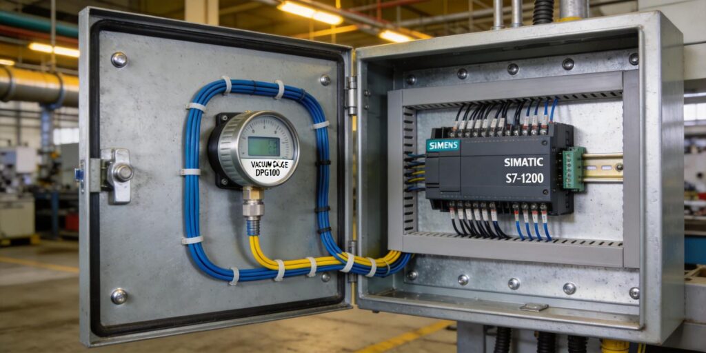
In automated vacuum systems, seamless integration of vacuum gauge signals into a programmable logic controller (PLC) is essential for reliable process monitoring, interlocks, and data logging. Siemens PLCs—particularly the popular S7-1200 and S7-1500 series—offer robust analog input capabilities that pair exceptionally well with industrial vacuum instrumentation. At Poseidon Scientific, our VG-SP205 Pirani Vacuum Transmitter and VG-SM225 Cold Cathode Vacuum Transmitter deliver clean 0–10 V analog outputs (effective range 2–8 V) alongside customizable RS-232 digital communication, making them straightforward to incorporate into Siemens-based control architectures.
This article provides a practical guide for engineers and system integrators on optimizing vacuum gauge signal integration with Siemens PLCs. We cover hardware configuration, signal scaling (including the common 4–20 mA standard), noise filtering, alarm logic, HMI visualization, redundancy strategies, and a ready-to-adapt ladder logic example. Whether you are retrofitting an existing line or designing a new mass-spectrometer or vacuum furnace control system, these techniques will help you achieve stable, repeatable pressure readings with minimal commissioning time.
Common PLC Analog Input Configuration
Siemens S7-1200 CPUs and expansion modules (such as the SM 1231 analog input modules) support both voltage and current signals through software-configurable channels in TIA Portal. For Poseidon gauges, which output 0–10 V DC, configure the channel for the 0–10 V range. In TIA Portal, open the device configuration, select the analog input module, and set the measurement type to “U” (voltage) with the range “0…10 V.” The raw digital value returned by the PLC will span 0 to 27,648, where 0 V equals 0 and 10 V equals 27,648.
If your plant standard is 4–20 mA (common in legacy instrumentation loops), Poseidon gauges can interface via a simple external signal converter (0–10 V to 4–20 mA). In this case, configure the PLC channel for “I” (current) with the 4–20 mA range. The raw value will then map from approximately 5,530 (4 mA) to 27,648 (20 mA). Proper wiring—using shielded twisted-pair cable and maintaining a common ground—prevents ground loops and ensures signal integrity over distances up to 100 m.
Hardware Wiring Best Practices
Connect the gauge’s analog output directly to the PLC’s positive input terminal and the gauge’s 0 V reference to the module’s common (M) terminal. Enable channel diagnostics in TIA Portal to catch open circuits or over-range conditions automatically. For the VG-SM225 cold cathode gauge, the high-voltage section remains fully isolated from the signal output, eliminating any risk of interference with low-level PLC inputs.
Scaling 4-20mA Signals (and 0-10V Equivalents)
Raw analog values must be converted to engineering units (typically Torr or Pa) before use in control logic. Siemens provides the standardized NORM_X and SCALE_X instructions for this purpose, available in both ladder and structured text.
For a Poseidon 0–10 V gauge (raw 0–27,648):
- Use NORM_X to convert the raw integer to a normalized REAL value (0.0–1.0).
- Use SCALE_X to map the normalized value to your vacuum range (e.g., 760 Torr to 10-3 Torr for the VG-SP205 Pirani).
The equivalent formula in TIA Portal is:
Normalized = (Raw - Min_Raw) / (Max_Raw - Min_Raw)
Scaled_Value = (Normalized × (Max_Eng - Min_Eng)) + Min_Eng
For 4–20 mA loops (raw 5,530–27,648), adjust Min_Raw accordingly. Poseidon’s technical datasheets include exact scaling constants for both the VG-SP205 and VG-SM225, ensuring linear correspondence in the primary operating bands. These pre-calibrated values eliminate guesswork and accelerate commissioning.
Filtering Noise in Analog Vacuum Signals
Vacuum gauge signals can contain electrical noise from nearby motors, RF sources, or plasma ignition transients (especially with the VG-SM225). Siemens PLCs offer several software filtering options without additional hardware.
A simple moving-average filter is highly effective and easy to implement. In ladder logic, maintain a FIFO buffer of the last 8–16 samples and compute the average on each scan cycle. This reduces high-frequency noise while preserving response time critical for vacuum interlocks. For more aggressive smoothing, the exponential filter (first-order low-pass) can be coded with minimal CPU load:
Filtered = (Alpha × New_Value) + ((1 - Alpha) × Filtered_Previous)
Where Alpha is typically 0.1–0.3. Test filter parameters during system commissioning using the PLC’s online trend function in TIA Portal to balance responsiveness and stability.
Alarm Threshold Programming
Vacuum systems require fast, reliable alarms for over-pressure, under-pressure, or gauge failure. In the PLC, use simple compare instructions (CMP) on the scaled pressure value. For example:
- High-pressure alarm: Scaled_Value > 1.0 × 10⁻² Torr (Pirani crossover point)
- Low-pressure alarm: Scaled_Value < 1.0 × 10⁻⁶ Torr (cold cathode limit)
Implement hysteresis (deadband) to prevent chattering—typically 5–10 % of the threshold. Link alarms to digital outputs for pump shutdown, valve closure, or audible/visual annunciation. Poseidon gauges also transmit status flags via RS-232 (e.g., high-voltage active, contamination warning), which can be read into the PLC as additional safety interlocks.
HMI Display Configuration
Siemens Comfort Panels or WinCC Unified HMIs integrate directly with the PLC tags. In TIA Portal, create a pressure display object bound to the scaled REAL value. Use dynamic color coding:
- Green: normal operating range
- Yellow: approaching alarm threshold
- Red: active alarm
Add trend charts for historical vacuum data and alarm banners that automatically pop up on fault conditions. For multi-gauge systems, configure faceplates that display both Pirani and cold cathode readings side-by-side, with automatic range switching at the 10-3 Torr crossover. The VG-SP205 and VG-SM225’s 0–10 V outputs ensure smooth, flicker-free updates on the HMI without additional scaling on the visualization side.
Redundancy Logic for Critical Applications
In semiconductor tools or high-value analytical instruments, dual-gauge redundancy improves availability. Program a simple voting logic block:
- Monitor both primary and backup gauge scaled values.
- If the primary deviates more than 10 % from the backup for three consecutive scans, switch to the backup and trigger a maintenance alarm.
- Use the average of both gauges for control when both are healthy.
This approach is easily coded in a reusable function block (FB) and requires only one additional analog input channel. Poseidon’s compact sensor size and low power draw make dual installations practical even in space-constrained chambers.
Example Ladder Logic Approach
Below is a simplified ladder logic snippet (exportable from TIA Portal) for scaling, filtering, and alarming a Poseidon gauge signal. Assume the raw analog input is at IW64 (S7-1200 analog word):
Network 1: Normalize raw value
NORM_X
IN := "Raw_Analog"   // IW64
OUT := "Normalized"  // REAL

Network 2: Scale to engineering units (example: 760 to 1E-3 Torr)
SCALE_X
IN := "Normalized"
MIN := 760.0
MAX := 0.001
OUT := "Pressure_Torr"  // REAL

Network 3: Moving average filter (8 samples)
"Filtered_Pressure" := ("Filtered_Pressure" * 7 + "Pressure_Torr") / 8

Network 4: High-pressure alarm with hysteresis
IF "Filtered_Pressure" > 0.05 THEN
    "High_Pressure_Alarm" := TRUE;
ELSIF "Filtered_Pressure" < 0.04 THEN
    "High_Pressure_Alarm" := FALSE;
END_IF
This structure runs in OB1 or a cyclic interrupt OB and consumes negligible cycle time. Full project archives with Poseidon-specific scaling constants are available from our applications team upon request.
Why Proper Integration Matters for Vacuum Performance
Accurate PLC integration does more than display numbers—it protects turbomolecular pumps, maintains process repeatability, and prevents costly downtime. Poseidon Scientific’s gauges were designed from the ground up for OEM and industrial automation: compact footprints, robust 0–10 V outputs, and fully customizable digital protocols (minimum 5–10 units). By following the configuration, scaling, and filtering practices outlined here, users routinely achieve measurement stability within ±3 % across the full operating temperature range.
Our VG-SP205 Pirani and VG-SM225 Cold Cathode transmitters have been successfully deployed in Siemens-controlled mass spectrometers and vacuum furnaces worldwide, delivering the low-cost, high-reliability performance that modern vacuum systems demand.
Need wiring diagrams, sample TIA Portal projects, or protocol customization for your exact Siemens setup? Our engineering support team is ready to assist. Download the latest datasheets for the VG-SP205 Pirani Vacuum Transmitter and VG-SM225 Cold Cathode Vacuum Gauge, or contact us directly to schedule a technical review of your integration requirements. From signal conditioning to full system validation, Poseidon Scientific is your partner for optimized vacuum measurement in Siemens PLC environments.

