Pressure Rise Test Methodology
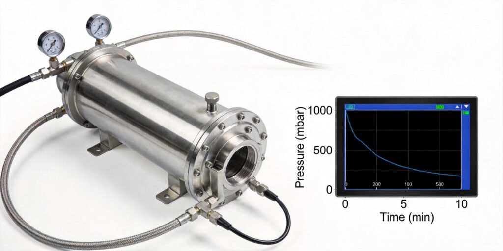
The pressure rise test is one of the most sensitive and widely used methods for detecting leaks in vacuum systems. After the chamber reaches a stable base pressure, the pump is isolated (typically with a valve) and the rate of pressure increase is monitored over time. Any real leak—whether from seals, welds, or virtual leaks—will cause a measurable rise that exceeds the system’s normal outgassing rate. The test is simple, repeatable, and requires no additional equipment beyond a reliable vacuum gauge and a timer.
In practice, the chamber is first evacuated to the target base pressure, isolated, and allowed to “soak” for 5–30 minutes while pressure is logged. The slope of the rise (ΔP/Δt) directly indicates leak rate. Poseidon Scientific’s VG-SP205 Pirani Vacuum Transmitter excels during the initial roughing and mid-vacuum phases of this test, while the VG-SM225 Cold Cathode Vacuum Gauge provides the stability and resolution needed at deeper vacuum levels where small leaks become critical. Continuous RS232 digital logging from either gauge turns the test into quantitative data rather than a visual guess.
Optimal Sensor Position
Gauge placement is the single most important factor in leak detection sensitivity. The sensor must be positioned where it can “see” the entire chamber volume without being shielded by baffles, fixtures, or long tubing runs. Ideal locations include a dedicated port on the chamber dome or side wall, away from direct pump lines and in a region of good gas conductance.
For most impregnation, coating, and heat-treatment chambers, mount the gauge 20–40 cm from the pump port using a short, high-conductance KF16 or KF25 nipple. The VG-SM225 Cold Cathode’s compact positive-magnetron design fits easily in tight manifolds while still delivering representative readings. Avoid placing the gauge directly opposite the pump inlet, where backstreaming or turbulent flow can mask small pressure changes. This positioning ensures the gauge captures true chamber pressure rise rather than localized artifacts.
Avoiding Dead Volume Effects
Dead volumes—trapped spaces behind valves, in blind flanges, or inside long sensor tubulations—create artificial pressure lags that reduce test sensitivity. A small leak in the main chamber may take minutes to register in a gauge connected through a narrow or lengthy tube, leading to false-negative results or inflated acceptance times.
Best practice is to keep the gauge connection as short and wide as possible (maximum 10–15 cm of ½-inch tubing) and to eliminate unnecessary valves between the gauge and chamber. The modular sensor head of the VG-SM225 allows direct flange mounting without extension tubes in most cases. During test setup, engineers should verify that the effective conductance between gauge and chamber exceeds the expected leak rate by at least two orders of magnitude. This simple geometric consideration routinely improves detection sensitivity from 10⁻⁴ Torr·L/s down to 10⁻⁶ Torr·L/s or better.
Minimizing Pump Backstreaming Influence
Oil-sealed rotary vane or diffusion pumps can introduce backstreaming hydrocarbons that slowly raise chamber pressure even in a leak-free system. During a pressure rise test this creates a false-positive slope that masks real leaks or forces overly conservative acceptance criteria.
To minimize backstreaming, isolate the high-vacuum pump completely before the test and allow the roughing pump (if still running) to operate only on a foreline trap. The VG-SP205 Pirani is particularly useful here because its thermal-conductivity measurement is insensitive to the low levels of oil vapor that affect ionization gauges. When a cold-cathode gauge is used, the VG-SM225’s built-in software protection and field-cleanable electrodes ensure that occasional backstreaming does not require immediate service. Many facilities now add a liquid-nitrogen or molecular-sieve trap on the foreline to further reduce this background rise.
Data Recording Tips
Accurate leak detection requires consistent, high-resolution data. Use the RS232 digital output on both Poseidon gauges to log pressure at 1–10 Hz directly into a PLC, SCADA, or simple spreadsheet. This eliminates manual stopwatch readings and provides a permanent, auditable record for quality systems.
Key tips include:
- Record both temperature and pressure simultaneously—temperature compensation in the VG-SP205 and VG-SM225 already accounts for ambient drift, but logging the value allows post-test correction if needed.
- Apply a 30–60 second moving-average filter to smooth short-term noise without masking genuine leaks.
- Export the raw time-stamped data for linear regression analysis; the slope of the best-fit line gives the true leak rate in Torr·L/s.
These practices turn a qualitative test into a quantitative, repeatable measurement that can be trended over months to predict seal wear before failure occurs.
Acceptance Criteria Example
Clear, application-specific acceptance criteria prevent subjective interpretation. A typical pressure rise test for a 200-liter impregnation chamber might use the following limits after 15 minutes of isolation:
| Base Pressure Before Test | Maximum Allowed Rise (15 min) | Equivalent Leak Rate | Action |
|---|---|---|---|
| < 5 × 10⁻⁴ Torr | 2 × 10⁻⁴ Torr | < 4 × 10⁻⁶ Torr·L/s | Pass – proceed to resin infusion |
| 5 × 10⁻⁴ to 1 × 10⁻³ Torr | 5 × 10⁻⁴ Torr | < 1 × 10⁻⁵ Torr·L/s | Conditional pass – monitor next cycle |
| > 1 × 10⁻³ Torr | Any rise > 1 × 10⁻³ Torr | > 2 × 10⁻⁵ Torr·L/s | Fail – locate and repair leak |
These limits are easily programmed into the PLC using the digital output of either gauge. Poseidon’s customizable RS232 protocol allows direct mapping of status codes and pressure values to existing acceptance logic, ensuring consistent pass/fail decisions across shifts and sites.
Case Analysis
A North American aerospace casting supplier repeatedly failed pressure rise tests on a 500-liter impregnation chamber despite thorough visual inspections. Initial troubleshooting showed a slow rise of 8 × 10⁻⁴ Torr over 15 minutes—well above the 2 × 10⁻⁴ Torr limit. The gauges were relocated from long 1-meter tubulations to direct chamber-wall ports, dead volumes behind blind flanges were eliminated, and a foreline trap was added to the roughing pump. Within one shift the rise dropped to 1.2 × 10⁻⁴ Torr, allowing the chamber to pass every subsequent test.
The root cause was a combination of poor gauge placement and backstreaming, not an actual leak. After standardizing the Poseidon dual-gauge installation (VG-SP205 for mid-range monitoring and VG-SM225 for final verification), first-pass acceptance rate rose from 68 % to 97 %, scrap costs fell by $180,000 annually, and unplanned downtime for leak chasing was virtually eliminated. The same optimized layout has since been adopted on three additional chambers, proving the long-term value of correct sensor placement and test methodology.
Conclusion: Maximize Leak Detection Sensitivity Through Proper Gauge Placement
Leak detection sensitivity is not limited by gauge specification alone—it is governed by how and where the gauge is installed. By following the pressure rise test methodology, positioning sensors for maximum conductance, eliminating dead volumes, minimizing backstreaming, and recording data digitally, engineers can reliably detect leaks down to 10⁻⁶ Torr·L/s or better using standard production equipment.
Poseidon Scientific’s VG-SP205 Pirani Vacuum Transmitter and VG-SM225 Cold Cathode Vacuum Gauge are designed with these real-world requirements in mind: compact footprints for optimal mounting, field-serviceable modular heads, temperature compensation, and fully customizable RS232 outputs that make high-resolution data logging effortless. Their combination of accuracy, ruggedness, and low total cost of ownership makes them the practical choice for vacuum impregnation, coating, and heat-treatment systems where leak integrity directly determines product quality.
Ready to improve leak detection sensitivity in your vacuum systems? Contact Poseidon Scientific today for a no-obligation installation review. Our team—led by the engineers who designed the VG-SP205 and VG-SM225—will examine your chamber drawings, current gauge locations, and test procedures and deliver a customized placement and methodology package that maximizes sensitivity while minimizing downtime.
Explore the full specifications of the VG-SP205 Pirani Vacuum Transmitter for mid-range monitoring or the VG-SM225 Cold Cathode Vacuum Gauge and take the next step toward faster, more reliable leak detection in your vacuum processes.

