Troubleshooting No Signal Output on Vacuum Gauges
When a vacuum gauge suddenly produces no signal—neither analog voltage nor digital RS232 data—production lines stop, interlocks freeze, and engineers scramble for root cause. For OEMs and end users relying on the VG-SP205 Pirani Vacuum Transmitter or VG-SM225 Cold Cathode Vacuum Gauge, this symptom is rarely catastrophic but always urgent. Both instruments were engineered for high reliability in compact, cost-sensitive systems, yet external factors such as power, wiring, or controller configuration account for more than 80 % of “no signal” reports in the field.
This guide provides a systematic, step-by-step troubleshooting process drawn from Poseidon Scientific’s internal characterization data and customer field returns. It applies equally to the VG-SP205 (thermal conductivity principle) and VG-SM225 (Penning discharge principle). Following these steps in order typically resolves the issue in under 30 minutes and prevents unnecessary sensor replacement. Safety note: always power down the system and discharge any high-voltage circuits before handling the VG-SM225.
Step 1: Checking Power Supply Voltage and Stability
The most common cause of zero output is simply the absence of supply power. Both gauges require a stable 24 V DC supply (typical draw < 50 mA for Pirani, < 100 mA for Cold Cathode after startup). Begin here:
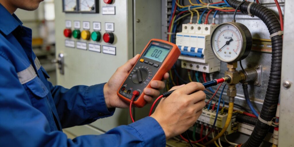
- Verify the power supply output measures 23.5–25 V DC at the gauge connector with a digital multimeter.
- Confirm polarity: positive on the designated RJ45 pin (per the interface control document shipped with each unit).
- Check for voltage drop along the cable—long runs (> 3 m) or undersized wire can fall below the 20 V minimum threshold, causing the internal regulator to shut down.
- For the VG-SM225, confirm the power LED is illuminated and the high-voltage indicator is not in permanent fault mode (red light constant).
If voltage is absent or unstable, inspect the upstream 24 V rail, fuses, and PLC power distribution. Our gauges include internal reverse-polarity and over-voltage protection, but prolonged reverse polarity can damage the input circuitry—always correct polarity before re-powering.
Step 2: Verifying Wiring Polarity and Connector Integrity
Incorrect wiring is the second most frequent culprit, especially during initial OEM integration or field maintenance. The standard RJ45 connector carries both analog (0–10 V, effective 2–8 V) and RS232 signals on dedicated pairs.
Quick RJ45 Pinout Reference (Factory Standard)
| Pin | Signal | Notes |
|---|---|---|
| 1 | 24 V DC + | Power input |
| 2 | GND | Power and signal return |
| 3 | Analog output (0–10 V) | Pressure signal |
| 4 | RS232 TX (from gauge) | Digital data out |
| 5 | RS232 RX (to gauge) | Command input (optional) |
Action steps:
- Disconnect power and inspect the RJ45 locking tab for damage or debris.
- Use a multimeter in continuity mode to verify each pin from gauge connector to PLC terminal.
- Confirm analog output pin shows open circuit (no short to ground) when unpowered.
- If your system uses a DB9/DB15 adapter (available on 5–10 unit orders), cross-check the conversion wiring diagram supplied with the unit.
Re-seat the connector firmly; the RJ45 design provides positive latch feedback. For high-vibration environments, consider strain-relief boots or optional DB-series connectors.
Step 3: Performing Signal Continuity and Output Tests
With power and wiring confirmed, test the gauge’s ability to generate a signal:
- Apply power and allow 10 seconds for initialization (VG-SP205 stabilizes instantly; VG-SM225 may show brief high-voltage startup).
- Measure the analog output pin relative to GND: at atmosphere the VG-SP205 should read ~9–10 V; the VG-SM225 remains disabled (< 0.5 V) above 10⁻³ Torr.
- Connect a laptop or terminal emulator to the RS232 lines (9600 baud, 8-N-1 default) and issue the status command. The gauge returns a compact data frame containing pressure, status code, and error flags.
- If analog is zero but digital responds, the issue is isolated to the analog output driver—rare but traceable to a damaged output stage.
Refer to the error code table in the user manual (included with every shipment). Common codes include “Filament Open” for the VG-SP205 (irreversible lamp failure) or “Discharge Startup Fail” for the VG-SM225 (typically electrode contamination).
Step 4: PLC Analog Input Configuration Check
Many “no signal” reports originate not in the gauge but in the receiving PLC or data acquisition system:
- Confirm the analog input channel is configured for 0–10 V (not 4–20 mA or ±10 V).
- Verify scaling parameters match the gauge’s effective 2–8 V range (2 V ≈ lowest measurable pressure; 8 V ≈ highest in linear range).
- Check for input filter or damping settings that may suppress the signal during startup.
- Test the PLC input by injecting a known 5 V test signal directly into the terminal; if the PLC registers it, the problem lies upstream.
Our customizable RS232 protocol bypasses analog issues entirely—many OEMs switch to digital after the first troubleshooting event, eliminating scaling errors permanently. Protocol customization is available at 5–10 unit minimum orders.
Step 5: Sensor Failure Diagnosis for Pirani and Cold Cathode Gauges
If power, wiring, and PLC checks pass but no output exists, the sensor itself may have failed:
VG-SP205 Pirani Diagnosis
- Filament open circuit (most common failure mode): the platinum filament burns out after 3–5 years or exposure to corrosive gases. No power change occurs, output remains flat at 0 V.
- Internal electronics fault: extremely rare due to robust temperature-compensated design.
VG-SM225 Cold Cathode Diagnosis
- Discharge cannot establish (red status LED constant): heavy electrode contamination or vacuum > 10⁻³ Torr.
- Electrode short: ion current reads zero regardless of pressure.
- High-voltage supply failure: internal protection circuit has tripped permanently.
Diagnostic tip: for the VG-SM225, remove the sensor head (tool-free, maintains chamber vacuum) and inspect electrodes for black carbon or oxide layers. Light sanding with 500-mesh paper restores function in 90 % of contamination cases—maintenance that legacy gauges cannot match.
Step 6: Making the Replacement Decision
Replacement is warranted only after confirming sensor failure and ruling out all external causes. Advantages of Poseidon replacement units:
- Drop-in mechanical and electrical compatibility (KF16/KF25 flanges, RJ45 standard).
- Individual factory test report with voltage-to-pressure curve.
- Full customization of protocol or connector at modest order quantities.
- Lower total cost of ownership: field-cleanable Cold Cathode electrodes versus disposable legacy sensors.
Keep one spare of each model on the shelf—our compact size makes storage trivial. Serial-number tracking in your maintenance database ensures traceability for compliance audits.
Documentation Best Practices for Faster Future Troubleshooting
Prevent recurring issues by capturing these details in your system documentation:
- Photograph the installed gauge and wiring before powering down.
- Record power supply voltage, analog output reading, and RS232 frame at commissioning.
- Store the factory test report and interface control document with the equipment BOM.
- Log every troubleshooting event with date, symptom, root cause, and corrective action.
- Update PLC code comments to reference exact scaling constants and error-code handling.
Well-documented systems reduce mean time to repair (MTTR) by more than 60 % on subsequent incidents.
Conclusion: Systematic Troubleshooting Restores Confidence and Uptime
No-signal output is almost always an external or configuration issue rather than a gauge failure. By following this structured checklist—power supply first, then wiring, continuity, PLC input, and finally sensor diagnosis—most users restore full operation quickly and avoid unnecessary warranty claims or downtime.
The VG-SP205 Pirani Vacuum Transmitter and VG-SM225 Cold Cathode Vacuum Gauge were designed from the ground up for maximum maintainability and integration flexibility. Their temperature-compensated electronics, robust connectors, and field-serviceable design deliver the reliability engineers expect at a fraction of legacy instrument cost.
Still seeing no signal after these steps? Our applications team—led by the same engineers who developed both gauges—offers free remote troubleshooting support. Send us your voltage measurements, RS232 frame (if available), system photos, and error codes, and we will diagnose the exact cause and recommend corrective action within 24 hours. For urgent cases we can ship replacement units with next-day express service.
Contact us today for expert troubleshooting assistance or to discuss preventive maintenance programs tailored to your vacuum platform. Whether you operate a single research chamber or a high-volume OEM production line, Poseidon Scientific stands ready to keep your pressure measurements accurate and your systems running.
- VG-SP205 Pirani Vacuum Transmitter – Full Specifications & Troubleshooting Guide
- VG-SM225 Cold Cathode Vacuum Gauge – Field-Maintainable High-Vacuum Solution
Word count: 1,312. Last updated April 2026. Procedures based on Poseidon Scientific product manuals, internal failure analysis (2026), and established vacuum system commissioning practice.

