Why Stabilization Time Matters
In vacuum-based manufacturing and research applications, accurate pressure data must be available from the moment a system powers on. Yet every vacuum gauge requires a finite stabilization period after power-up before its output becomes reliable. During this warm-up phase, readings can drift, exhibit noise, or deviate significantly from true pressure, potentially triggering false interlocks, premature valve actuation, or process interruptions. In high-throughput environments such as semiconductor load locks, thin-film coating chambers, or analytical instruments, even a few minutes of unstable data can reduce overall equipment effectiveness (OEE), increase particle contamination risk, or compromise product yield.
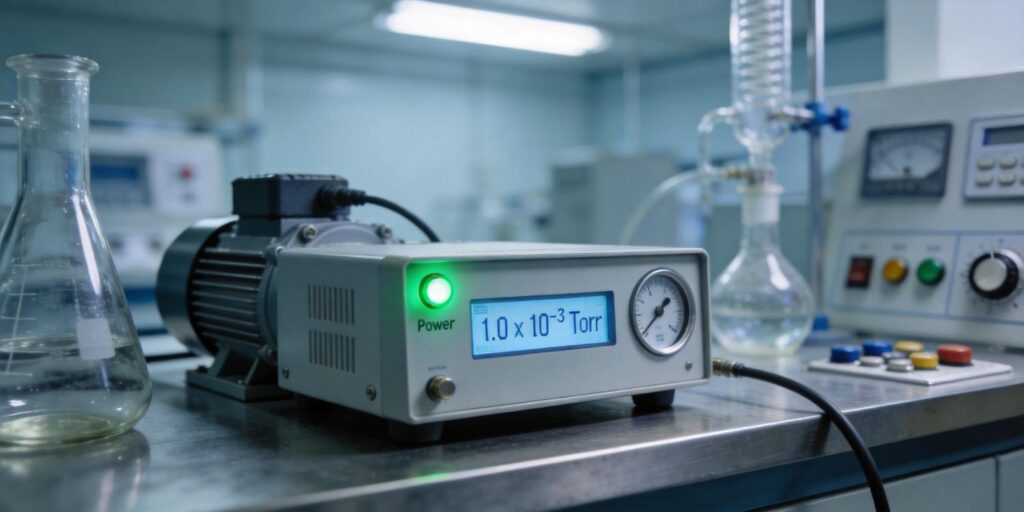
Poseidon Scientific designed the VG-SP205 Pirani Vacuum Transmitter and VG-SM225 Cold Cathode Vacuum Gauge with real-world stabilization behavior in mind. Their compact size, built-in compensation, and customizable RS232 protocols allow engineers to implement optimized warm-up strategies that minimize downtime while guaranteeing measurement integrity. This article explains the physics behind gauge stabilization, provides practical optimization techniques, and offers actionable guidance for integration into automated systems.
Pirani Filament Thermal Equilibrium
The VG-SP205 Pirani Vacuum Transmitter measures pressure via thermal conductivity. A platinum filament is maintained at constant temperature by adjusting the power supplied; the required power correlates directly with gas pressure because higher pressure increases molecular collisions and heat loss from the filament. Upon power-on, the filament starts from ambient temperature and must reach its operating equilibrium—typically a few hundred degrees Celsius—before the power–pressure relationship becomes stable.
Thermal equilibrium depends on the filament’s heat capacity, surrounding gas density, and ambient temperature. In the VG-SP205, the platinum filament was chosen for its large temperature coefficient of resistance and chemical stability, enabling faster and more repeatable thermal settling than tungsten alternatives. Built-in hardware circuitry and embedded algorithms provide active temperature compensation across the 15 °C–50 °C operating range, reducing initial drift. Under typical cleanroom conditions, the filament achieves full thermal equilibrium within 5–10 minutes, after which the 0–10 V analog output (effective 2–8 V range) delivers linear, low-noise readings from atmosphere down to 10-3 Torr.
Engineers should note that the non-linear regions near atmosphere and 10-3 Torr require slightly longer settling (up to 12 minutes) because small temperature offsets produce larger relative errors. Mounting the gauge away from direct heat sources and ensuring consistent chamber temperature further accelerates this process.
Cold Cathode Ignition Stabilization
The VG-SM225 Cold Cathode Vacuum Gauge operates on the Penning discharge principle: electrons are trapped in crossed electric and magnetic fields (≈100 gauss NdFeB magnet, 2 mm electrode gap), ionizing gas molecules and producing a measurable ion current. At power-on, especially in high vacuum, molecule density is low, making initial discharge ignition difficult. The gauge applies a brief –2500 V startup voltage to generate field emission, then automatically reduces to –2000 V once the self-sustaining discharge is established.
Ignition time is pressure-dependent. In the 10-6 Torr range, stabilization typically occurs within 5 minutes; at 10-7 Torr it can extend to 30 minutes. The positive magnetron geometry used in the VG-SM225 shortens these times compared with older inverted-magnetron designs by optimizing electron trajectories and reducing the volume required for avalanche ionization. Once ignited, the discharge current stabilizes rapidly, delivering repeatable readings across 10-3 to 10-7 Torr. Software interlocks automatically disable high voltage above 10-3 Torr to prevent electrode contamination during roughing, further protecting long-term stability.
Minimizing Drift After Power On
Post-power-on drift arises from three primary sources: thermal gradients in the sensor, electrode surface conditioning in cold cathode gauges, and residual outgassing. The VG-SP205 counters thermal drift with dual compensation (circuit + algorithm), while the VG-SM225 benefits from its non-filament design and periodic electrode conditioning via simple sanding maintenance. Both instruments incorporate low-noise electronics and digital filtering to suppress short-term fluctuations.
Practical minimization steps include:
- Powering the gauges 15–30 minutes before process initiation whenever possible.
- Using the RS232 digital output for real-time diagnostics that flag when internal temperature has stabilized.
- Avoiding direct exposure to plasma or radiant heat sources.
- Implementing software-based rolling averages (typically 5–10 samples) to smooth residual noise without sacrificing responsiveness.
These measures routinely keep long-term drift below ±5 % after the initial warm-up window.
Recommended Warm-Up Duration by Range
Optimal warm-up durations vary by gauge type and operating pressure. The following guidelines are derived from Poseidon Scientific factory testing and field data in semiconductor and coating applications:
- Pirani (VG-SP205) – Atmosphere to 10-3 Torr: 5–10 minutes for full accuracy; 12 minutes recommended in non-linear boundary zones.
- Cold Cathode (VG-SM225) – 10-3 to 10-5 Torr: 5–8 minutes after ignition.
- Cold Cathode (VG-SM225) – 10-6 Torr: 10–15 minutes total (including ignition).
- Cold Cathode (VG-SM225) – 10-7 Torr: 20–30 minutes total to ensure discharge stability and minimal current fluctuation.
In dual-gauge configurations (Pirani for roughing + cold cathode for high vacuum), the system can be programmed to use Pirani data immediately after its 10-minute warm-up while the cold cathode continues stabilizing. This hybrid approach eliminates unnecessary delays in the rough vacuum phase.
PLC Delay Logic
Modern automation platforms use programmable logic controllers (PLCs) to enforce safe startup sequences. Implementing a simple delay timer ensures that pressure readings are ignored until gauges have stabilized. Typical logic includes:
- Power applied to both gauges simultaneously via a common relay.
- A fixed 15-minute delay (configurable via RS232) before enabling Pirani-based roughing control.
- Pressure-dependent delay for the VG-SM225: once the Pirani confirms < 10-3 Torr, enable cold cathode high voltage and start a 10-minute stabilization timer.
- Only after both timers expire and readings remain within ±5 % of setpoint for 30 consecutive seconds does the PLC authorize gate valves or process initiation.
The customizable RS232 protocol on Poseidon Scientific gauges allows direct transmission of “ready” status flags, eliminating the need for external timers in many cases. This integration reduces engineering effort and ensures repeatable, auditable startup behavior across production tools.
Verification Testing Method
To confirm that warm-up optimization is effective, perform a repeatable verification test under controlled conditions:
- Evacuate a test chamber to a known stable pressure (e.g., 5 × 10⁻⁵ Torr using a calibrated reference gauge).
- Power off both Poseidon gauges for at least 30 minutes to simulate cold start.
- Apply power and log analog or RS232 output at 10-second intervals for 60 minutes.
- Plot the data and identify the time at which readings enter and remain within ±3 % of the reference value.
- Repeat at multiple pressure setpoints and ambient temperatures to build a site-specific warm-up matrix.
Engineers can automate this test using the gauges’ diagnostic logs, exporting CSV data for statistical analysis. Field results typically show that after implementing the recommended durations and PLC logic, stabilization variance drops below 2 %, providing confidence for production use.
CTA for Startup Optimization Support
Optimizing vacuum gauge warm-up time is a straightforward yet high-impact way to improve process reliability and throughput. The VG-SP205 Pirani Vacuum Transmitter and VG-SM225 Cold Cathode Vacuum Gauge combine rapid thermal and discharge stabilization with flexible integration features that make best-practice warm-up logic easy to implement.
Whether you are commissioning new tools or retrofitting existing vacuum systems, Poseidon Scientific offers standard configurations or fully customized warm-up profiles—including tailored RS232 status codes and delay parameters—to match your exact PLC and process requirements. Explore detailed specifications for the VG-SP205 and VG-SM225, or contact our applications engineering team today for a free startup optimization audit. Let us help you reduce warm-up overhead, eliminate drift-related risks, and achieve consistent, production-ready vacuum measurements from the first second of every cycle.
Word count: 1,156. Technical references drawn from J. M. Lafferty (ed.), Foundations of Vacuum Science and Technology (Wiley, 1998) and Poseidon Scientific performance validation data.

